


Ultra-simple Voltage Probe
#voltage probe
#LED indicator
#polarity detection
#AC voltage
#DC voltage
#current limiting
#simple circuit
#DIY electronics
#test equipment
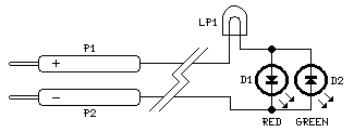
Description: This circuit is not a novelty, but it proved so useful, simple and cheap that it is worth building. When the positive (Red) probe is connected to a DC positive voltage and the Black probe to the negative, the Red LED will illuminate. Reversing polarities the Green LED will illuminate. Connecting the probes to an AC source both LEDs will go on. The bulb limits the LEDs current to 40mA @ 220V AC and its filament starts illuminating from about 30V, shining more brightly as voltage increases.
This circuit functions as a simple voltage indicator with dual LED outputs to signify different conditions based on the type of voltage applied. It utilizes two light-emitting diodes (LEDs) – one red and one green – to provide visual feedback regarding the polarity of the voltage being measured and whether it is AC or DC.
The circuit is designed to operate with a DC voltage source. When the positive probe (typically colored red) is connected to the positive terminal of a DC source, the red LED will illuminate. This indicates a proper connection to a positive voltage. Conversely, if the probes are reversed, with the red probe connected to the negative terminal, the green LED will illuminate, indicating reverse polarity.
In the case of an AC voltage source, both LEDs will illuminate simultaneously. This feature allows for quick identification of AC voltage presence, as both LEDs do not light up under DC conditions unless the polarity is reversed.
A crucial component of this circuit is the inclusion of a current-limiting bulb that ensures the LEDs do not exceed their maximum current rating of 40mA, particularly when connected to high AC voltages, such as 220V. The bulb serves two purposes: it limits the current flowing through the LEDs and provides a visual indication of voltage presence. The filament of the bulb begins to glow at approximately 30V AC, becoming brighter as the voltage increases. This characteristic can be useful for applications requiring a visual confirmation of voltage levels.
The circuit's simplicity and low cost make it an attractive option for electrical testing and educational purposes, allowing users to easily identify voltage types and conditions without the need for complex instrumentation.This circuit is not a novelty, but it proved so useful, simple and cheap that it is worth building. When the positive (Red) probe is connected to a DC positive voltage and the Black probe to the negative, the Red LED will illuminate. Reversing polarities the Green LED will illuminate. Connecting the probes to an AC source both LEDs will go on. The bulb limits the LEDs current to 40mA @ 220V AC and its filament starts illuminating from about 30V, shining more brightly as voltage increases.
This circuit functions as a simple voltage indicator with dual LED outputs to signify different conditions based on the type of voltage applied. It utilizes two light-emitting diodes (LEDs) – one red and one green – to provide visual feedback regarding the polarity of the voltage being measured and whether it is AC or DC.
The circuit is designed to operate with a DC voltage source. When the positive probe (typically colored red) is connected to the positive terminal of a DC source, the red LED will illuminate. This indicates a proper connection to a positive voltage. Conversely, if the probes are reversed, with the red probe connected to the negative terminal, the green LED will illuminate, indicating reverse polarity.
In the case of an AC voltage source, both LEDs will illuminate simultaneously. This feature allows for quick identification of AC voltage presence, as both LEDs do not light up under DC conditions unless the polarity is reversed.
A crucial component of this circuit is the inclusion of a current-limiting bulb that ensures the LEDs do not exceed their maximum current rating of 40mA, particularly when connected to high AC voltages, such as 220V. The bulb serves two purposes: it limits the current flowing through the LEDs and provides a visual indication of voltage presence. The filament of the bulb begins to glow at approximately 30V AC, becoming brighter as the voltage increases. This characteristic can be useful for applications requiring a visual confirmation of voltage levels.
The circuit's simplicity and low cost make it an attractive option for electrical testing and educational purposes, allowing users to easily identify voltage types and conditions without the need for complex instrumentation.This circuit is not a novelty, but it proved so useful, simple and cheap that it is worth building. When the positive (Red) probe is connected to a DC positive voltage and the Black probe to the negative, the Red LED will illuminate. Reversing polarities the Green LED will illuminate. Connecting the probes to an AC source both LEDs will go on. The bulb limits the LEDs current to 40mA @ 220V AC and its filament starts illuminating from about 30V, shining more brightly as voltage increases.
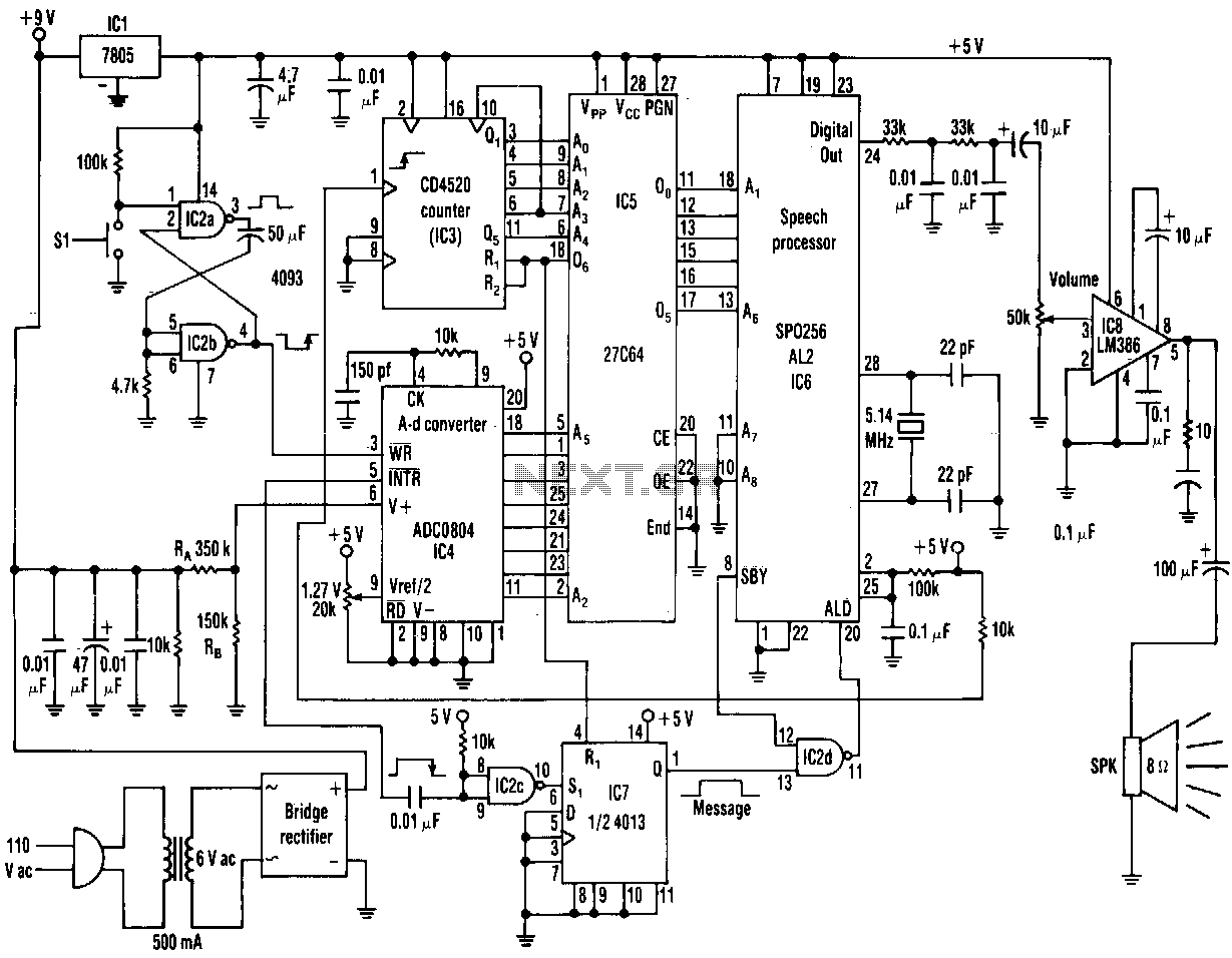
Ac-line-voltage-announcer
The range of this AC voltage monitor is 100 to 140 Vac, with a resolution of 1 V. The speech processor interprets an 8-bit binary input code from an analog-to-digital converter. The processor's pulse-code-modulated output then passes through a filter...
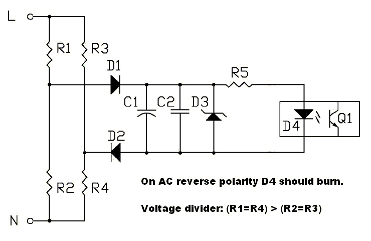
AC polarity detection
The circuit should be capable of detecting voltages between 230 VAC and 120 VAC to 250 VAC, making it suitable for both US and EU applications. A non-isolated circuit was found, but it fails to simulate correctly due to ground...
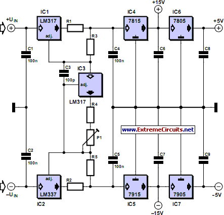
adjustable current limit for dual power
This current-limiting circuit, illustrated as part of a small bench power supply, can be utilized with any dual-rail current source. The section of the circuit on the left limits the current entering the dual voltage regulator (IC4 to IC7) to...
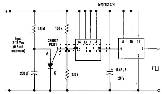
Dc Output Chopper Circuit
A direct current (DC) voltage source within the range of 2 to 15 volts can be converted into a unipolar square wave. This square wave has a peak amplitude that is nearly equal to the DC source voltage, with lightly...
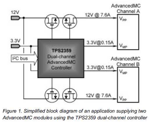
Current Limiting for Redundant Power Systems
The new TPS2359 hot-plug controller integrates all power management functions for two AdvancedMC (AMC) modules. Its current limiting circuitry enables designers to meet stringent AMC requirements, particularly in applications utilizing redundant supplies. A unique feature called multiswap maintains a fixed...
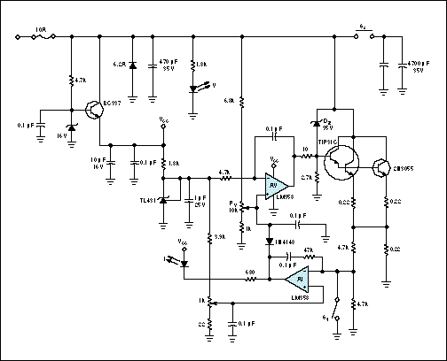
Battery simulator provides current limiting
A constant-voltage active load can function as a battery during the charge cycle. The load voltage can be adjusted from 5 to 35V using potentiometer PV, simulating batteries with voltages ranging from 6 to 32V. In the testing of a...
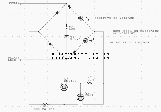
Voltage Test Probe
Using inexpensive components, you can fit a simple probe circuit into a pencil-sized enclosure. When both LEDs are on, the probe indicates the presence of an ac voltage; either LED alone indicates the presence and polarity of a dc voltage....
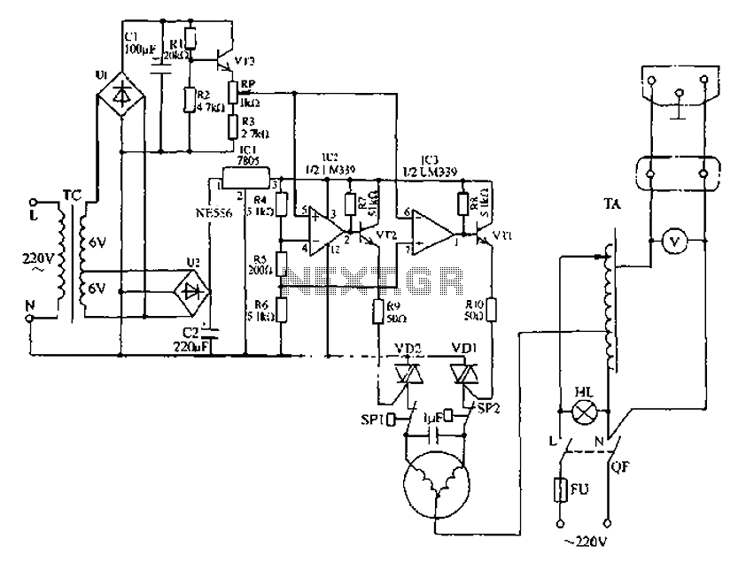
Automatic AC voltage regulator circuit
Automatic AC voltage regulator circuit
The automatic AC voltage regulator circuit is designed to maintain a stable output voltage despite fluctuations in the input voltage. This circuit is essential for protecting sensitive electronic devices from voltage variations that can lead to...
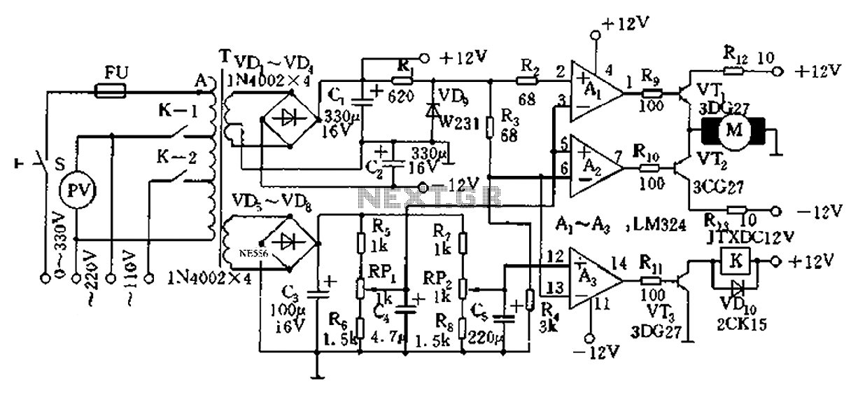
Automatic AC voltage regulator circuit TXD1742 continuous adjustment
Automatic AC voltage regulator circuit TXD1742 with continuous adjustment.
The TXD1742 is an automatic AC voltage regulator circuit designed to provide continuous voltage adjustment, ensuring stable output voltage in varying load conditions. This circuit is particularly useful in applications where voltage...