


Voltage Test Probe
#voltage probe
#LED indicator
#AC voltage
#DC voltage
#diode bridge
#test circuit
#measurement tool
#electronics testing
#simple probe
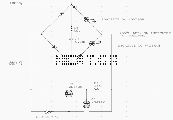
Description: Using inexpensive components, you can fit a simple probe circuit into a pencil-sized enclosure. When both LEDs are on, the probe indicates the presence of an ac voltage; either LED alone indicates the presence and polarity of a dc voltage. The diode-bridge arrangement allows one-way current source R1, R2, Q1, and Q2 to light either LED (or both) when the probe is activated by a test voltage. More: Diodes provide the necessary peak-inverse voltage rating; R3 and C1 provide a spike-suppression network to protect the current-source transistors.
The described probe circuit is a compact and efficient device designed to detect both alternating current (AC) and direct current (DC) voltages. The circuit utilizes a simple arrangement of components to achieve its functionality, making it suitable for a variety of applications in electrical testing.
The core of the circuit consists of a diode bridge, which is essential for converting AC voltage to a usable form for the LEDs. The diodes in the bridge configuration ensure that the circuit can handle the reverse voltage, providing the necessary peak-inverse voltage rating to protect against voltage spikes. This is particularly important in environments where the probe may encounter fluctuating voltages.
The circuit includes two light-emitting diodes (LEDs), which serve as visual indicators of voltage presence and polarity. When both LEDs are illuminated, it indicates that an AC voltage is present. In contrast, if only one LED lights up, it signifies the presence of a DC voltage, with the specific LED indicating the polarity of the voltage. This dual functionality allows the user to quickly ascertain the type of voltage being tested.
Resistors R1 and R2 are part of a current source configuration that helps to regulate the current flowing through the LEDs. The values of these resistors can be selected based on the desired brightness of the LEDs and the specific voltage range being tested.
Transistors Q1 and Q2 are employed to amplify the current from the diode bridge, ensuring that the LEDs receive sufficient current to illuminate brightly. The choice of transistors should be based on their current rating and response time to ensure reliable operation in the presence of varying input voltages.
To protect the circuit from transient voltage spikes, a spike-suppression network comprising resistor R3 and capacitor C1 is included. This network serves to absorb sudden voltage changes, thereby safeguarding the sensitive components, particularly the transistors, from damage due to excessive voltage.
Overall, this simple probe circuit is a practical solution for voltage detection, leveraging inexpensive components and a straightforward design to provide reliable performance in a compact form factor. The integration of visual indicators and protection mechanisms enhances its usability and longevity in various electrical testing scenarios.Using inexpensive components, you can fit a simple probe circuit into a pencil-sized enclosure. When both LEDs are on, the probe indicates the presence of an ac voltage; either LED alone indicates the presence and polarity of a dc voltage. The diode-bridge arrangement allows one-way current source R1, R2, Q1, and Q2 to light either LED (or both) when the probe is activated by a test voltage.
Diodes provide the necessary peak-inverse voltage rating; R3 and C1 provide a spike-suppression network to protect the current-source transistors.
The described probe circuit is a compact and efficient device designed to detect both alternating current (AC) and direct current (DC) voltages. The circuit utilizes a simple arrangement of components to achieve its functionality, making it suitable for a variety of applications in electrical testing.
The core of the circuit consists of a diode bridge, which is essential for converting AC voltage to a usable form for the LEDs. The diodes in the bridge configuration ensure that the circuit can handle the reverse voltage, providing the necessary peak-inverse voltage rating to protect against voltage spikes. This is particularly important in environments where the probe may encounter fluctuating voltages.
The circuit includes two light-emitting diodes (LEDs), which serve as visual indicators of voltage presence and polarity. When both LEDs are illuminated, it indicates that an AC voltage is present. In contrast, if only one LED lights up, it signifies the presence of a DC voltage, with the specific LED indicating the polarity of the voltage. This dual functionality allows the user to quickly ascertain the type of voltage being tested.
Resistors R1 and R2 are part of a current source configuration that helps to regulate the current flowing through the LEDs. The values of these resistors can be selected based on the desired brightness of the LEDs and the specific voltage range being tested.
Transistors Q1 and Q2 are employed to amplify the current from the diode bridge, ensuring that the LEDs receive sufficient current to illuminate brightly. The choice of transistors should be based on their current rating and response time to ensure reliable operation in the presence of varying input voltages.
To protect the circuit from transient voltage spikes, a spike-suppression network comprising resistor R3 and capacitor C1 is included. This network serves to absorb sudden voltage changes, thereby safeguarding the sensitive components, particularly the transistors, from damage due to excessive voltage.
Overall, this simple probe circuit is a practical solution for voltage detection, leveraging inexpensive components and a straightforward design to provide reliable performance in a compact form factor. The integration of visual indicators and protection mechanisms enhances its usability and longevity in various electrical testing scenarios.Using inexpensive components, you can fit a simple probe circuit into a pencil-sized enclosure. When both LEDs are on, the probe indicates the presence of an ac voltage; either LED alone indicates the presence and polarity of a dc voltage. The diode-bridge arrangement allows one-way current source R1, R2, Q1, and Q2 to light either LED (or both) when the probe is activated by a test voltage.
Diodes provide the necessary peak-inverse voltage rating; R3 and C1 provide a spike-suppression network to protect the current-source transistors.
Audio Peak / Beat LED indicator
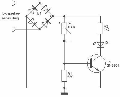
This indicator can be used, or see if your speakers can be damaged by the noise power. With P1 you can set the limit to which D1 LED lights. The pot is 100k here, you can even experiment with other...
High/Low Voltage Probe
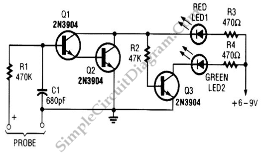
A simple voltage probe circuit is depicted in the schematic diagram below. This circuit is highly useful for testing or troubleshooting discrete or integrated circuits.
The simple voltage probe circuit serves as an essential tool for engineers and technicians engaged in...
Mains Voltage Probe
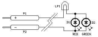
This circuit is not a novelty, but it proved so useful, simple and cheap that it is worth building. When the positive (Red) probe is connected to a DC positive voltage and the Black probe to the negative, the Red...
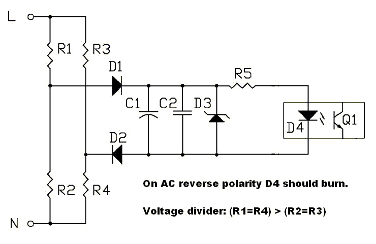
AC polarity detection
The circuit should be capable of detecting voltages between 230 VAC and 120 VAC to 250 VAC, making it suitable for both US and EU applications. A non-isolated circuit was found, but it fails to simulate correctly due to ground...
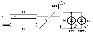
Ultra-simple Voltage Probe
This circuit is not a novelty, but it proved so useful, simple and cheap that it is worth building. When the positive (Red) probe is connected to a DC positive voltage and the Black probe to the negative, the Red...
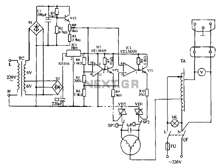
Automatic AC voltage regulator circuit
Automatic AC voltage regulator circuit
The automatic AC voltage regulator circuit is designed to maintain a stable output voltage despite fluctuations in the input voltage. This circuit is essential for protecting sensitive electronic devices from voltage variations that can lead to...
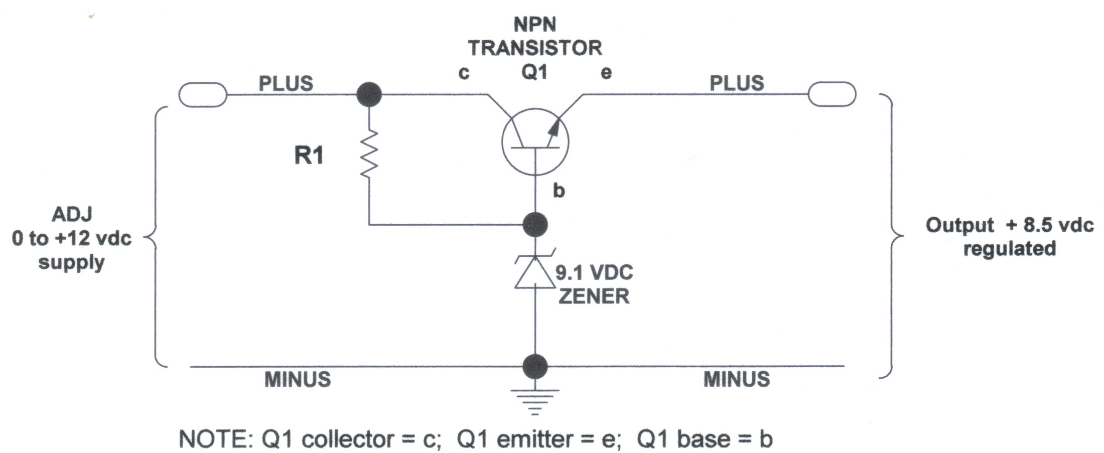
voltage regulators
DC Voltage Regulator (NPN & Zener Regulator) There are instances where it is handy to have a regulated DC voltage power supply for use on your model.
A DC voltage regulator is an essential component in electronic circuits that provides a...
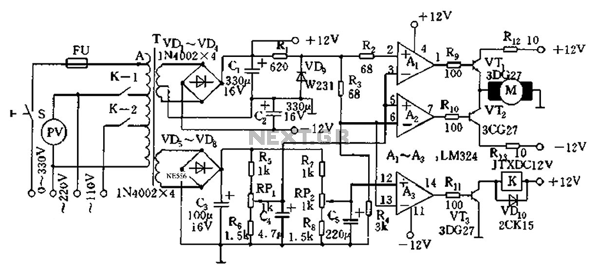
Automatic AC voltage regulator circuit TXD1742 continuous adjustment
Automatic AC voltage regulator circuit TXD1742 with continuous adjustment.
The TXD1742 is an automatic AC voltage regulator circuit designed to provide continuous voltage adjustment, ensuring stable output voltage in varying load conditions. This circuit is particularly useful in applications where voltage...
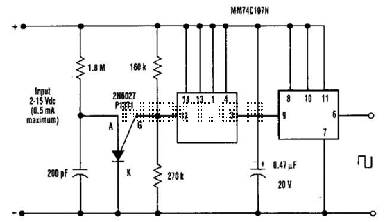
Dc Output Chopper Circuit
A direct current (DC) voltage source within the range of 2 to 15 volts can be converted into a unipolar square wave. This square wave has a peak amplitude that is nearly equal to the DC source voltage, with lightly...