


vhf dip meter
#VHF
#dip meter
#resonance
#LC circuit
#frequency measurement
#variable capacitor
#tester coil
#RF measurement
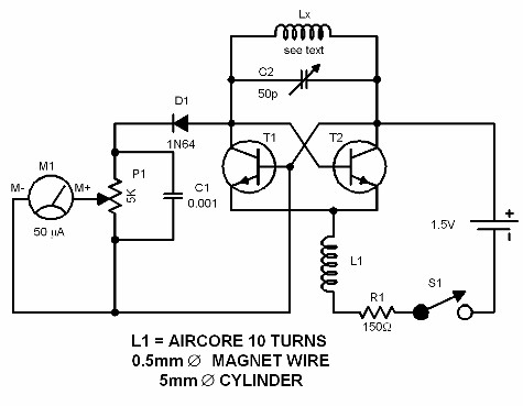
Description: A dip meter operates by measuring the resonance of an LC circuit. The circuit presented is designed for use in the VHF range. The tester coil is connected to the LX terminals and positioned near the LC circuit under examination. The variable capacitor C1 is adjusted gradually until a noticeable dip appears on the meter. The frequency or inductance can then be determined using the scale. This scale must be constructed using several LC circuits with known values. The most efficient method for calibrating the dip meter and creating the scale is to utilize a frequency counter. The tester coil consists of two turns of magnet wire, providing a frequency range of approximately 50 to 150 MHz.
The dip meter circuit is an essential tool for RF engineers and hobbyists, enabling precise measurements of inductance and frequency within the VHF spectrum. The core components of the circuit include a variable capacitor (C1), a tester coil, and a measurement meter that indicates the resonance dip. The tester coil, typically constructed with two turns of magnet wire, is critical for achieving the desired frequency range, which spans from 50 MHz to 150 MHz.
To utilize the dip meter effectively, the tester coil is inserted into the LX terminals, establishing a connection with the circuit under test. The positioning of the coil is crucial, as it must be placed near the LC circuit to ensure accurate resonance detection. The variable capacitor (C1) allows for fine-tuning of the circuit's resonant frequency. As the capacitor is adjusted, the dip meter displays a decrease in signal strength, indicating that resonance has been achieved.
Calibration of the dip meter is a vital step to ensure accurate readings. This process involves creating a scale based on known LC circuits, which serve as references for the measurements. A frequency counter can expedite this calibration process, providing precise frequency values that can be marked on the scale. This self-constructed scale is essential for interpreting the dip meter's readings correctly.
In summary, the dip meter is a valuable instrument for measuring the resonance of LC circuits in the VHF range. Its design, consisting of a tester coil, variable capacitor, and calibrated scale, allows for accurate determination of frequency and inductance, making it an indispensable tool in the field of electronics.We all know how a dip meter works and what it measures - the resonance of an LC circuit. The circuit featured here is designed to work in the VHF range. The tester coil is inserted in the LX terminals and placed near the LC circuit to be tested. The variable capacitor C1 is slowly turned until a substantial dip is observed in the meter. The freque ncy (or the inductance) can then be read on the scale. The scale must be self constructed by using several LC circuits with known values. The fastest way to calibrate the dip meter (or to make the scale) is to use a frequency counter. The tester coil is 2 turns magnet wire. This gives a frequency range of around 50. 150 MHz.
The dip meter circuit is an essential tool for RF engineers and hobbyists, enabling precise measurements of inductance and frequency within the VHF spectrum. The core components of the circuit include a variable capacitor (C1), a tester coil, and a measurement meter that indicates the resonance dip. The tester coil, typically constructed with two turns of magnet wire, is critical for achieving the desired frequency range, which spans from 50 MHz to 150 MHz.
To utilize the dip meter effectively, the tester coil is inserted into the LX terminals, establishing a connection with the circuit under test. The positioning of the coil is crucial, as it must be placed near the LC circuit to ensure accurate resonance detection. The variable capacitor (C1) allows for fine-tuning of the circuit's resonant frequency. As the capacitor is adjusted, the dip meter displays a decrease in signal strength, indicating that resonance has been achieved.
Calibration of the dip meter is a vital step to ensure accurate readings. This process involves creating a scale based on known LC circuits, which serve as references for the measurements. A frequency counter can expedite this calibration process, providing precise frequency values that can be marked on the scale. This self-constructed scale is essential for interpreting the dip meter's readings correctly.
In summary, the dip meter is a valuable instrument for measuring the resonance of LC circuits in the VHF range. Its design, consisting of a tester coil, variable capacitor, and calibrated scale, allows for accurate determination of frequency and inductance, making it an indispensable tool in the field of electronics.We all know how a dip meter works and what it measures - the resonance of an LC circuit. The circuit featured here is designed to work in the VHF range. The tester coil is inserted in the LX terminals and placed near the LC circuit to be tested. The variable capacitor C1 is slowly turned until a substantial dip is observed in the meter. The freque ncy (or the inductance) can then be read on the scale. The scale must be self constructed by using several LC circuits with known values. The fastest way to calibrate the dip meter (or to make the scale) is to use a frequency counter. The tester coil is 2 turns magnet wire. This gives a frequency range of around 50. 150 MHz.
Amateur Radio circuits
For the shorter wavelength VHF and UHF bands, it is more practical to construct complex antennas such as a single-band Slim Jim or Yagis. Various projects include creating an electronic unit, as it is necessary for the Intermediate Level license...
VHF 5/8wave vertical antennas
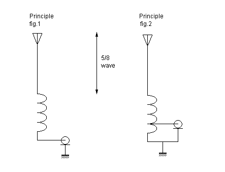
At VHF, both the 1/4-wavelength monopole and the 5/8-wavelength monopole antennas are widely used. The VHF 5/8-wavelength (144 MHz) vertical monopole has long held the reputation of providing about a 3-dB gain advantage over the 1/4-wavelength vertical monopole. The foundation...
low noise vhf uhf oscillators
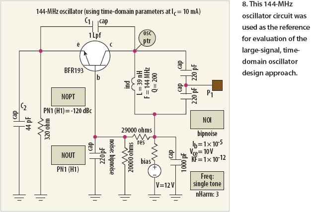
Unlike conventional small-signal methods, employing large-signal, time-domain design techniques facilitates the creation of low-noise grounded-base oscillators suitable for VHF/UHF applications.
The development of low-noise grounded-base oscillators for VHF/UHF applications presents unique challenges and opportunities. By utilizing large-signal, time-domain design techniques, engineers...
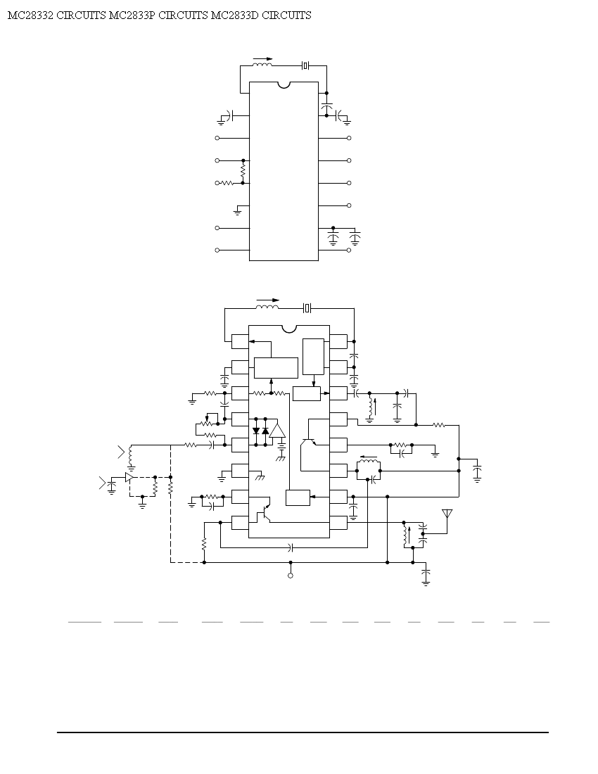
MC28332 Single Chip VHF Narrowband FM Transmitter Application Circuit
Crystal X1 operates in fundamental mode and is calibrated for parallel resonance with a load capacitance of 32 pF. The final output frequency is produced through frequency multiplication within the MC2833 integrated circuit (IC). The RF output buffer at Pin...
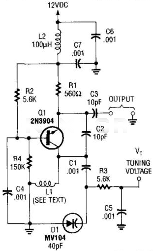
Voltage-Tuned Vhf Oscillator
This VHF VCO circuit operates within the frequency range of 30 to 200 MHz. Q1 may be substituted with a 2N3563 for frequencies exceeding 100 MHz. The inductor, L1, is selected to resonate at the desired frequency in conjunction with...
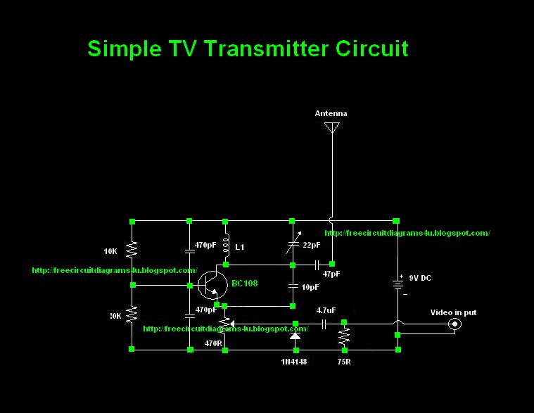
TV Transmitter circuit diagram (VHF)
Many individuals inquire about TV transmitters. This document provides a useful circuit diagram that enables signal transmission over distances of 75 to 100 meters. The circuit diagram is not original; it was provided by a friend. Contributions of circuit diagrams...
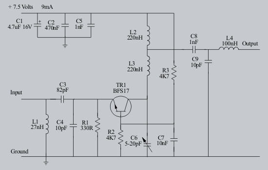
VHF Pre-Amplifier Circuits Diagram Using The BFS17 Transistor
The following circuit illustrates a VHF pre-amplifier circuit diagram. This circuit utilizes the BFS17 transistor. Features: designed for VHF applications.
The VHF pre-amplifier circuit is essential for enhancing weak radio frequency signals in the VHF (Very High Frequency) range, typically between...
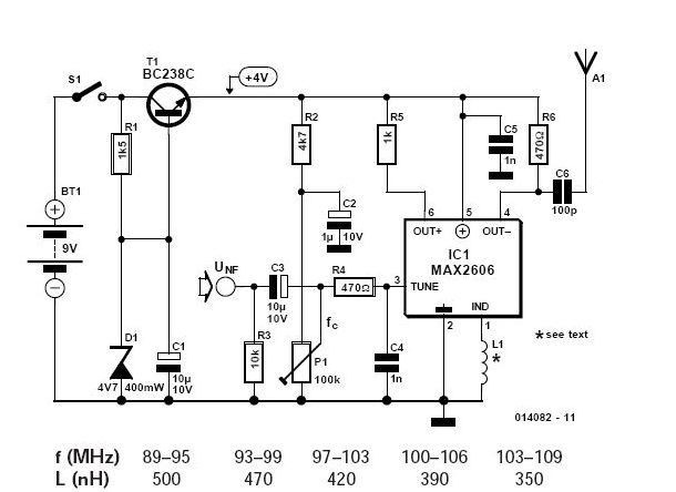
VHF FM Transmitter MAX2606
To achieve independence from local radio stations when testing VHF receivers, a frequency-modulated oscillator is required that operates within the range of 89.5 to 108 MHz. However, constructing such an oscillator using discrete components can be quite challenging. Maxim has...
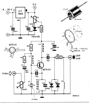
VHF/UHF TV modulator
A TV modulator is really no more than a transmitter. It is a very small transmitter, admittedly, but none the less that is what it is. What does a modulator actually do? In general - and this design is no...