


connect a lcd to the bottom half of a port
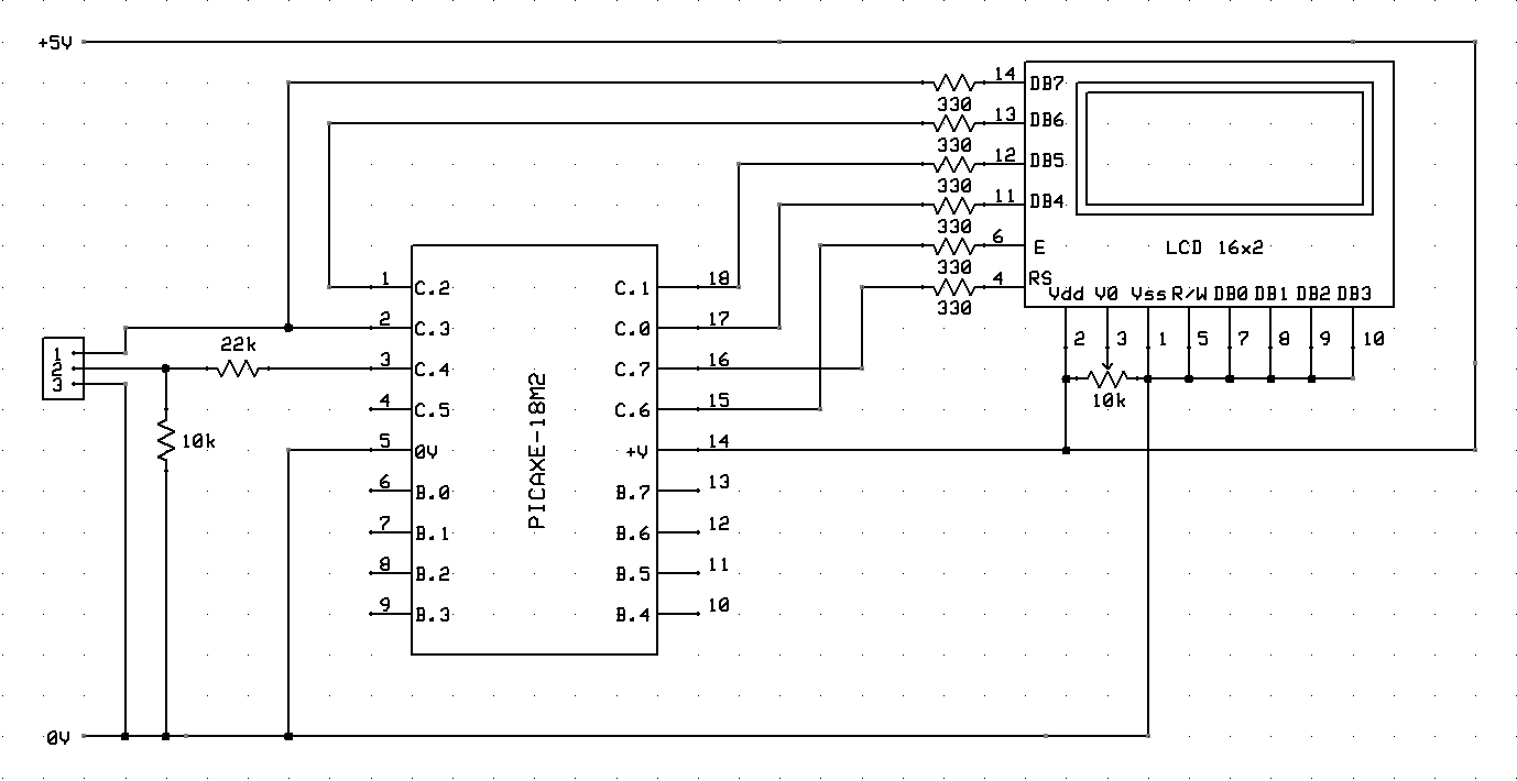
Description: The circuit diagram and code for connecting a 16x2 LCD to a PICAXE-18M2 microcontroller using the lower half of a port for the data lines.
The circuit involves interfacing a 16x2 LCD with a PICAXE-18M2 microcontroller, utilizing the lower half of a specified port for data communication. The LCD operates in 4-bit mode, which is advantageous for reducing the number of data lines required for communication, thus optimizing the circuit layout.
To establish the connection, the following pins of the LCD are utilized: RS (Register Select), RW (Read/Write), E (Enable), and four data pins (D4, D5, D6, D7). The PICAXE-18M2 microcontroller will interface with these pins as follows:
1. **RS Pin**: Connect to a designated output pin on the microcontroller, typically used to select between command and data modes.
2. **RW Pin**: This pin can be connected to ground, as the microcontroller will only be writing data to the LCD.
3. **E Pin**: Connect to another output pin on the microcontroller, used to enable the LCD to read the data presented on the data pins.
4. **Data Pins (D4-D7)**: Connect these pins to four output pins on the PICAXE-18M2, allowing for the transmission of data in 4-bit mode.
Power supply connections must be made to the LCD, ensuring proper voltage levels are maintained, typically +5V for standard LCDs. Additionally, a potentiometer may be used to adjust the contrast of the display.
The programming of the PICAXE-18M2 will include commands to initialize the LCD, set the cursor position, and send data to be displayed. The initialization sequence must follow the LCD's requirements, including function set, display control, and entry mode set commands.
This setup allows for effective communication and control of the LCD display, enabling the microcontroller to present information in a user-friendly manner. Proper attention to wiring and coding will ensure reliable operation of the circuit.The circuit diagram and code on how to connect an 16x2 LCD to a PICAXE-18M2 microcontroller using the lower half of a port for the data lines..
The circuit involves interfacing a 16x2 LCD with a PICAXE-18M2 microcontroller, utilizing the lower half of a specified port for data communication. The LCD operates in 4-bit mode, which is advantageous for reducing the number of data lines required for communication, thus optimizing the circuit layout.
To establish the connection, the following pins of the LCD are utilized: RS (Register Select), RW (Read/Write), E (Enable), and four data pins (D4, D5, D6, D7). The PICAXE-18M2 microcontroller will interface with these pins as follows:
1. **RS Pin**: Connect to a designated output pin on the microcontroller, typically used to select between command and data modes.
2. **RW Pin**: This pin can be connected to ground, as the microcontroller will only be writing data to the LCD.
3. **E Pin**: Connect to another output pin on the microcontroller, used to enable the LCD to read the data presented on the data pins.
4. **Data Pins (D4-D7)**: Connect these pins to four output pins on the PICAXE-18M2, allowing for the transmission of data in 4-bit mode.
Power supply connections must be made to the LCD, ensuring proper voltage levels are maintained, typically +5V for standard LCDs. Additionally, a potentiometer may be used to adjust the contrast of the display.
The programming of the PICAXE-18M2 will include commands to initialize the LCD, set the cursor position, and send data to be displayed. The initialization sequence must follow the LCD's requirements, including function set, display control, and entry mode set commands.
This setup allows for effective communication and control of the LCD display, enabling the microcontroller to present information in a user-friendly manner. Proper attention to wiring and coding will ensure reliable operation of the circuit.The circuit diagram and code on how to connect an 16x2 LCD to a PICAXE-18M2 microcontroller using the lower half of a port for the data lines..
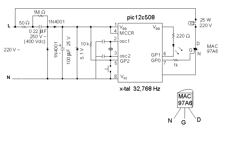
Night Light Saver
A Microchip PIC12C508 8-pin CMOS microcontroller controls a night light, turning it on and off at preset times every day. It is designed to save energy, produce no electromagnetic interference (EMI), and operate without batteries, featuring a built-in lamp fixture...
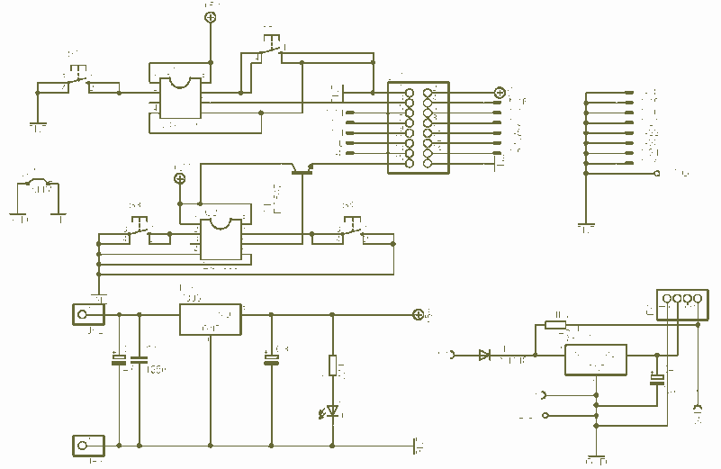
LCD to LPT board
The LCD2LPT with Lirc circuit is the compilation of two circuits found on the net on a single board. The first is LCD to LPT interface and the second an IR remote control interface using http://www.lirc.org program. The main circuit...
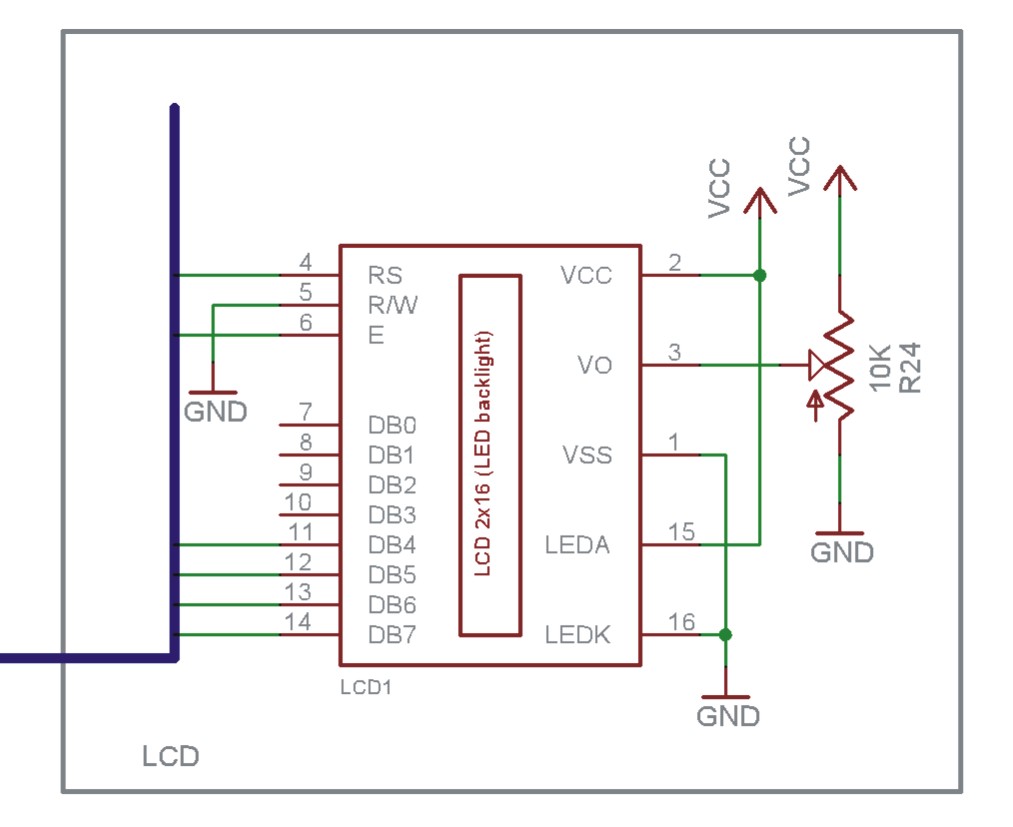
interfacing lcd
The EN line is referred to as 'Enable'. This control line is utilized to indicate to the LCD that data is being sent. To transmit data to the LCD, the program must ensure that this line is low (0), then...
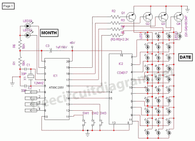
Digital Calender Circuit
This is a digital calendar circuit that utilizes a microcontroller to display the date, day, and month on an LED display. The entire system is managed by an 8-bit microcontroller, which operates based on a program embedded in its ROM....
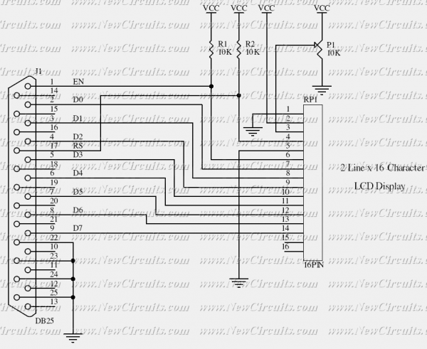
LCD Module Control with PC
This simple circuit controls a popular 2-line x 16-character LCD by a PC via printer port. It doesn't use the Bi-directional feature found on newer printer ports, thus it should work with most, if not all, Parallel Ports. These LCD...
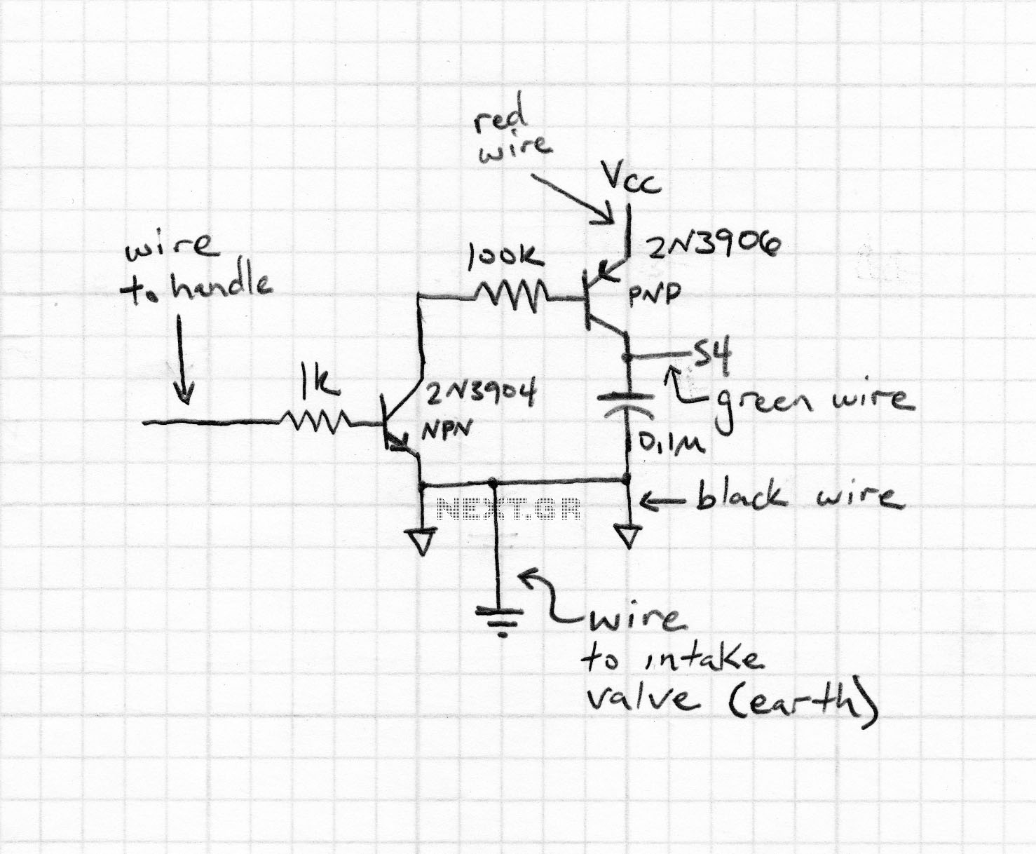
Microcontroller Voltmeter / Ammeter with LCD
The rectifier bridge voltage is determined by the U2 element; refer to its datasheet for the maximum voltage specifications. The minimum voltage at this pin should not fall below approximately 9V, or 6.5V if low-dropout type U2 and U3 voltage...
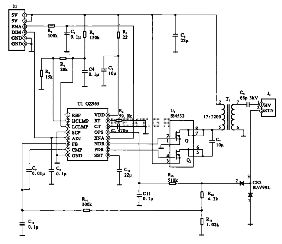
A typical liquid crystal display inverter circuit OZ965
A typical liquid crystal display inverter circuit (OZ965) is primarily controlled by the OZ965 chip. It includes a driving field effect transistor (U2), a step-up transformer, the backlight socket, and associated circuitry. A 5V DC voltage is provided by the...
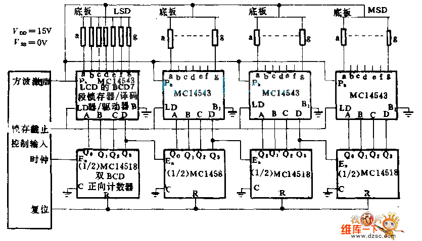
4 Direct drive LCD display circuit diagram
Each part of the LCD has an individual counter, latch, decoder, and driver. The pumping signal is fed back to the motherboard of the LCD. When the display section is disconnected, the phase and amplitude of the motherboard and display...
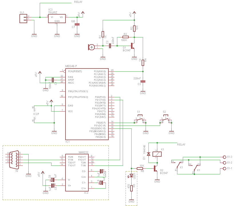
Microcontroller Clapper Switch
For those who prefer convenience, it is possible to turn the bedroom light on or off without leaving the bed simply by clapping hands. This concept inspired the design of a clap-activated light control system. Various clap switch projects can...