


PIC 16F88 Microcontroller PIC based Tengu
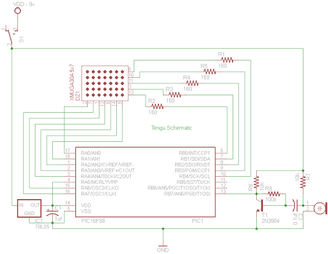
Description: Tengu derives its name from a mythical Japanese creature known for getting into mischief. However, this Tengu is more earthly in nature. It responds to voice and sounds, changing its facial features depending on the intensity of the sound. If no sound is detected for a period, it transitions from a happy face to a sad face and then goes to sleep. Gently blowing on its face wakes it back up to its usual happy self. The project is based on a Microchip PIC 16F88, which is part of their mid-range microcontrollers. The sound is amplified through a pre-amplifier circuit based on the 2N3904 transistor and fed to the RB7/AN6 (pin 13) of the PIC microcontroller. The A/D converter on the microcontroller is utilized to convert the analog signal from the pre-amplifier. The LED matrix is directly driven by the PIC. To display the entire smiley face, the LED dot matrix is multiplexed so that only one row out of the seven is active at any given time. However, the rows are activated and deactivated rapidly, creating the illusion of a full picture to the human eye, a phenomenon known as persistence of vision. To achieve multiplexing, Timer 0 on the PIC operates at approximately 1 ms timeouts to switch the displayed row on the LED matrix. Timer 1 is configured as a general-purpose timer to track the time since any noise exceeding the threshold was detected, which is used to change the smiley face from happy to sad. The code is written in C using the MPLAB and Hi-Tech C compiler version 9.80.
The Tengu project integrates various electronic components and programming techniques to create an interactive visual display that responds to sound. The core of the design is the Microchip PIC 16F88 microcontroller, which serves as the brain of the system. This microcontroller features an integrated Analog-to-Digital Converter (ADC) that allows for the conversion of analog signals from the pre-amplifier circuit into digital data for processing.
The pre-amplifier circuit, constructed using a 2N3904 transistor, amplifies the incoming audio signals, ensuring that even soft sounds can be detected by the microcontroller. The amplified signal is fed into pin RB7/AN6 of the PIC, where the ADC processes the input. The resulting digital signal is then analyzed to determine the intensity of the sound, which influences the facial expression displayed on the LED matrix.
The LED matrix is composed of seven rows, each capable of displaying part of the smiley face. The multiplexing technique employed allows for only one row to be activated at a time, with rapid switching between rows creating the perception of a complete image. This is facilitated by Timer 0, which is programmed to generate interrupts approximately every millisecond. This timing ensures that the switching occurs quickly enough to maintain the illusion of a continuous display.
Timer 1 plays a crucial role in monitoring the duration of silence. When the sound level drops below a predetermined threshold, Timer 1 starts counting. If the silence persists beyond a specific duration, the system triggers a change in the facial expression from happy to sad, indicating a lack of interaction. The transition back to a happy expression occurs when the system detects a sound, such as a gentle blow, which resets Timer 1.
The software for the Tengu project is developed in C using the MPLAB IDE alongside the Hi-Tech C compiler. The code implements the necessary logic for sound detection, facial expression management, and LED matrix control, ensuring a responsive and engaging user experience. Overall, the Tengu project combines sound sensing, visual display, and timing control to create a playful electronic device that captures the essence of its mythical namesake.Tengu derives its name from a mythicalJapanese creature known for getting intomischief. Our Tengu, however is more earthly in nature. It responds to voice and sounds and takes on different facial features depending on the intensity of the sound. If no sound is heard for some time, it changes from a happy face to a sad face and then goes to sleep.
G ently blowing on his face wakes him back up to his usual happy self. The project is based on a Microchip PIC 16F88 which is part of their mid range of microcontrollers. The sound is amplified through a pre-amp circuit based on 2N3904 and fed to the RB7/AN6 (pin 13) of the pic microcontroller. The A/D converter on the microcontroller is used to convert the analog signal from the pre-amp. The LED Matrix is directly driven by the pic. In order to be able to display the entire smiley, the LED dot matrix is multiplexed in such a way that only one row out of the seven is active at any given time.
However the rows are turned on and off so rapidly, the human eye sees it as a full picture. This effect is called the persistence of vision. In order to achieve multiplexing, timer 0 on the pic is running at approximately 1 ms timeouts to switch the row that is being displayed on the LED Matrix. Timer 1 is configured as a general purpose timer used to keep track of the time since any noise over the threshold was heard.
This is used to change the smiley from a happy to a sad one. The code is written in C using MPLAB and Hi-Tech C compiler ver 9. 80.
The Tengu project integrates various electronic components and programming techniques to create an interactive visual display that responds to sound. The core of the design is the Microchip PIC 16F88 microcontroller, which serves as the brain of the system. This microcontroller features an integrated Analog-to-Digital Converter (ADC) that allows for the conversion of analog signals from the pre-amplifier circuit into digital data for processing.
The pre-amplifier circuit, constructed using a 2N3904 transistor, amplifies the incoming audio signals, ensuring that even soft sounds can be detected by the microcontroller. The amplified signal is fed into pin RB7/AN6 of the PIC, where the ADC processes the input. The resulting digital signal is then analyzed to determine the intensity of the sound, which influences the facial expression displayed on the LED matrix.
The LED matrix is composed of seven rows, each capable of displaying part of the smiley face. The multiplexing technique employed allows for only one row to be activated at a time, with rapid switching between rows creating the perception of a complete image. This is facilitated by Timer 0, which is programmed to generate interrupts approximately every millisecond. This timing ensures that the switching occurs quickly enough to maintain the illusion of a continuous display.
Timer 1 plays a crucial role in monitoring the duration of silence. When the sound level drops below a predetermined threshold, Timer 1 starts counting. If the silence persists beyond a specific duration, the system triggers a change in the facial expression from happy to sad, indicating a lack of interaction. The transition back to a happy expression occurs when the system detects a sound, such as a gentle blow, which resets Timer 1.
The software for the Tengu project is developed in C using the MPLAB IDE alongside the Hi-Tech C compiler. The code implements the necessary logic for sound detection, facial expression management, and LED matrix control, ensuring a responsive and engaging user experience. Overall, the Tengu project combines sound sensing, visual display, and timing control to create a playful electronic device that captures the essence of its mythical namesake.Tengu derives its name from a mythicalJapanese creature known for getting intomischief. Our Tengu, however is more earthly in nature. It responds to voice and sounds and takes on different facial features depending on the intensity of the sound. If no sound is heard for some time, it changes from a happy face to a sad face and then goes to sleep.
G ently blowing on his face wakes him back up to his usual happy self. The project is based on a Microchip PIC 16F88 which is part of their mid range of microcontrollers. The sound is amplified through a pre-amp circuit based on 2N3904 and fed to the RB7/AN6 (pin 13) of the pic microcontroller. The A/D converter on the microcontroller is used to convert the analog signal from the pre-amp. The LED Matrix is directly driven by the pic. In order to be able to display the entire smiley, the LED dot matrix is multiplexed in such a way that only one row out of the seven is active at any given time.
However the rows are turned on and off so rapidly, the human eye sees it as a full picture. This effect is called the persistence of vision. In order to achieve multiplexing, timer 0 on the pic is running at approximately 1 ms timeouts to switch the row that is being displayed on the LED Matrix. Timer 1 is configured as a general purpose timer used to keep track of the time since any noise over the threshold was heard.
This is used to change the smiley from a happy to a sad one. The code is written in C using MPLAB and Hi-Tech C compiler ver 9. 80.
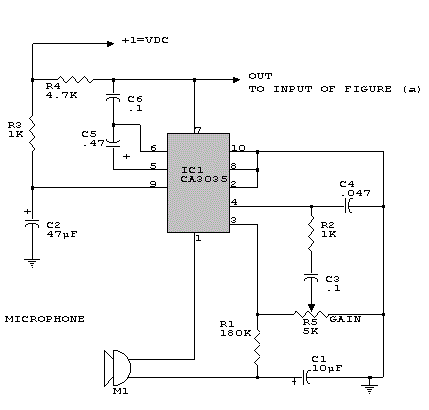
sound sensor schematics
This is a simple sound sensor schematic that utilizes a single integrated circuit (IC) and two transistors to drive a relay. The schematic allows for sensitivity adjustment using a variable resistor (VR). This design is quite useful and can be...
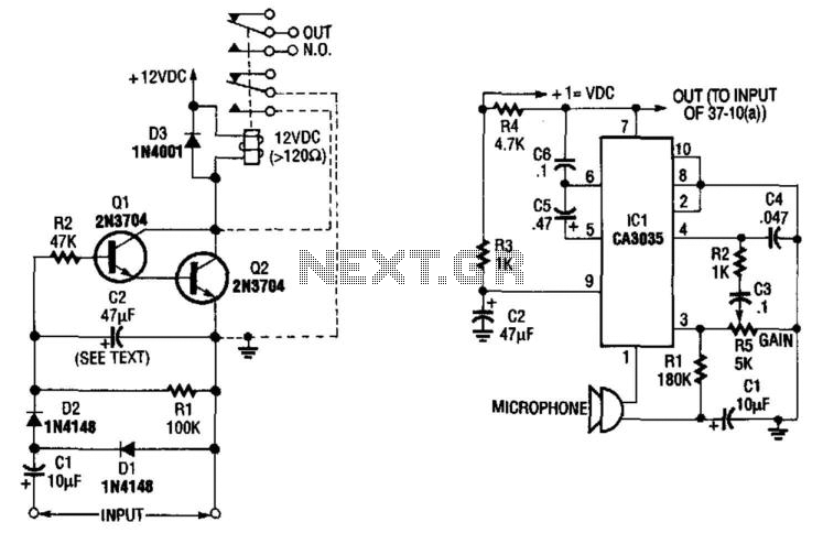
Sound Sensor
A sound-detecting alarm system can be constructed using a microphone, a high-gain amplifier, and a detector-relay driver. For a latching setup, connect the dotted lines to the relay as indicated in the schematic.
The sound-detecting alarm system utilizes a microphone to...

Voice dimmer
The VRbot is a voice recognition module featuring multiple functions. Its dimensions are approximately 1" x 1.75". The manufacturer offers a free GUI software called VRbot GUI for setting up user-defined commands. Since the input/output data for the VRbot operates...
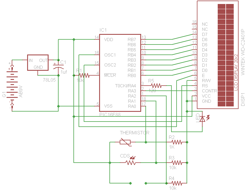
PIC 16F88 Digital Thermometer Light Meter and resistance ohm meter
The initial concept for this project involves interfacing the WINTEK WD-C2401P LCD panel with a PIC microcontroller. The intention is to incorporate several ADC readings to provide useful information on the LCD. PORTB on the PIC serves as the data...
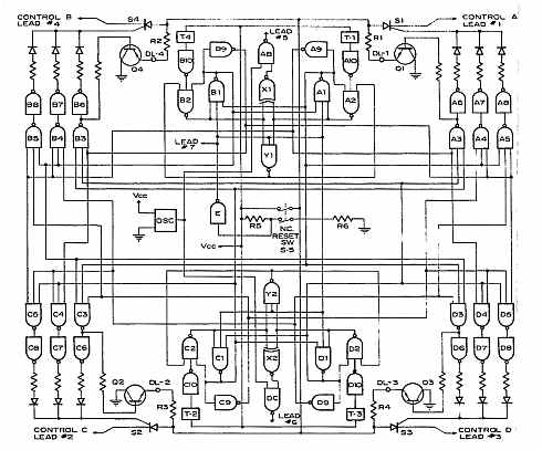
sound origin direction finder
A sound origin direction indicator features a flat square shape with four sound transducer/amplifier units positioned at each corner. It includes four rows of solid-state lamps extending from the center to the corners and an electronic system integrated with the...
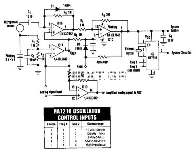
Sleep Mode Circuit Circuit
The HA7210 oscillator, in conjunction with the IOL7642 quad CMOS operational amplifier, forms a sleep-mode control circuit. This circuit can enter sleep mode when a logic high is applied to the Reset input or through an RC timer that facilitates...