


Small 3-wheel ROBOT with PIC16F84 brain & InfraRed eyes
#PIC16F84
#infrared
#robot
#motor control
#obstacle avoidance
#sensor
#embedded
#automation
#electronics
#DIY
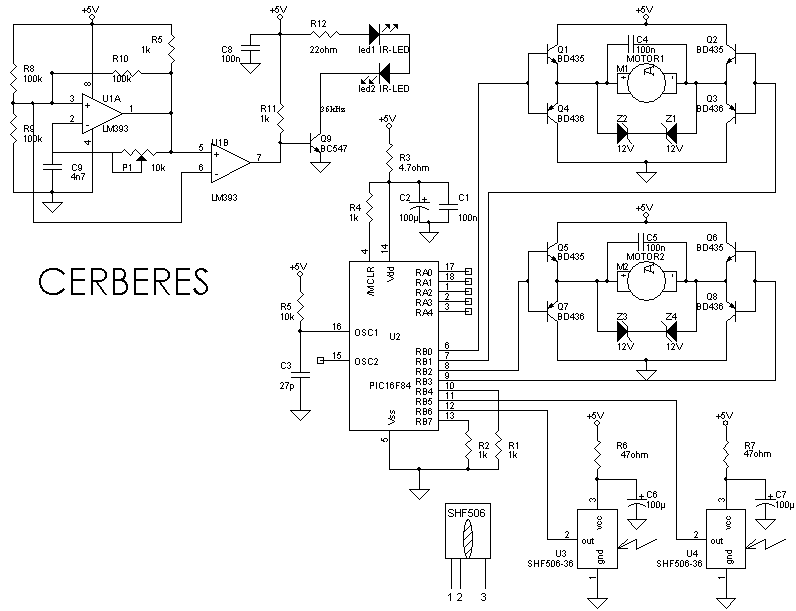
Description: When the 36 kHz infrared light emitted by the LEDs is reflected off an object, one of the receiver modules is activated. The PIC16F84 microcontroller then directs the robot to avoid the object by reversing one of the motors.
The circuit involves an infrared LED that emits light at a frequency of 36 kHz. This light travels until it encounters an object, where it is reflected back towards a photodetector or infrared receiver module. The photodetector is designed to be sensitive to the 36 kHz frequency, ensuring that it only activates in response to the reflected infrared light.
Upon receiving the reflected signal, the receiver module sends a signal to the PIC16F84 microcontroller. This microcontroller is programmed to interpret the input from the receiver module. In response to the signal, the microcontroller executes a control algorithm that determines the appropriate action for the robot. Specifically, it will reverse one of the motors to steer the robot away from the detected obstacle.
The circuit may also include additional components such as resistors for current limiting, capacitors for signal smoothing, and possibly a transistor or relay to control the motor's operation. The motor driver circuit is crucial as it interfaces between the microcontroller and the motors, allowing the low-power signals from the PIC16F84 to control the higher power requirements of the motors.
Overall, this design exemplifies a basic obstacle avoidance mechanism in robotic applications, utilizing infrared sensing technology and microcontroller logic to achieve autonomous navigation.When the 36 kHz infrared light from the LEDs is reflected by an object, one of the receiver modules will be triggered, and the PIC16F84 µController will steer the ROBOT away from the objects by reversing one of the motors.
The circuit involves an infrared LED that emits light at a frequency of 36 kHz. This light travels until it encounters an object, where it is reflected back towards a photodetector or infrared receiver module. The photodetector is designed to be sensitive to the 36 kHz frequency, ensuring that it only activates in response to the reflected infrared light.
Upon receiving the reflected signal, the receiver module sends a signal to the PIC16F84 microcontroller. This microcontroller is programmed to interpret the input from the receiver module. In response to the signal, the microcontroller executes a control algorithm that determines the appropriate action for the robot. Specifically, it will reverse one of the motors to steer the robot away from the detected obstacle.
The circuit may also include additional components such as resistors for current limiting, capacitors for signal smoothing, and possibly a transistor or relay to control the motor's operation. The motor driver circuit is crucial as it interfaces between the microcontroller and the motors, allowing the low-power signals from the PIC16F84 to control the higher power requirements of the motors.
Overall, this design exemplifies a basic obstacle avoidance mechanism in robotic applications, utilizing infrared sensing technology and microcontroller logic to achieve autonomous navigation.When the 36 kHz infrared light from the LEDs is reflected by an object, one of the receiver modules will be triggered, and the PIC16F84 µController will steer the ROBOT away from the objects by reversing one of the motors.
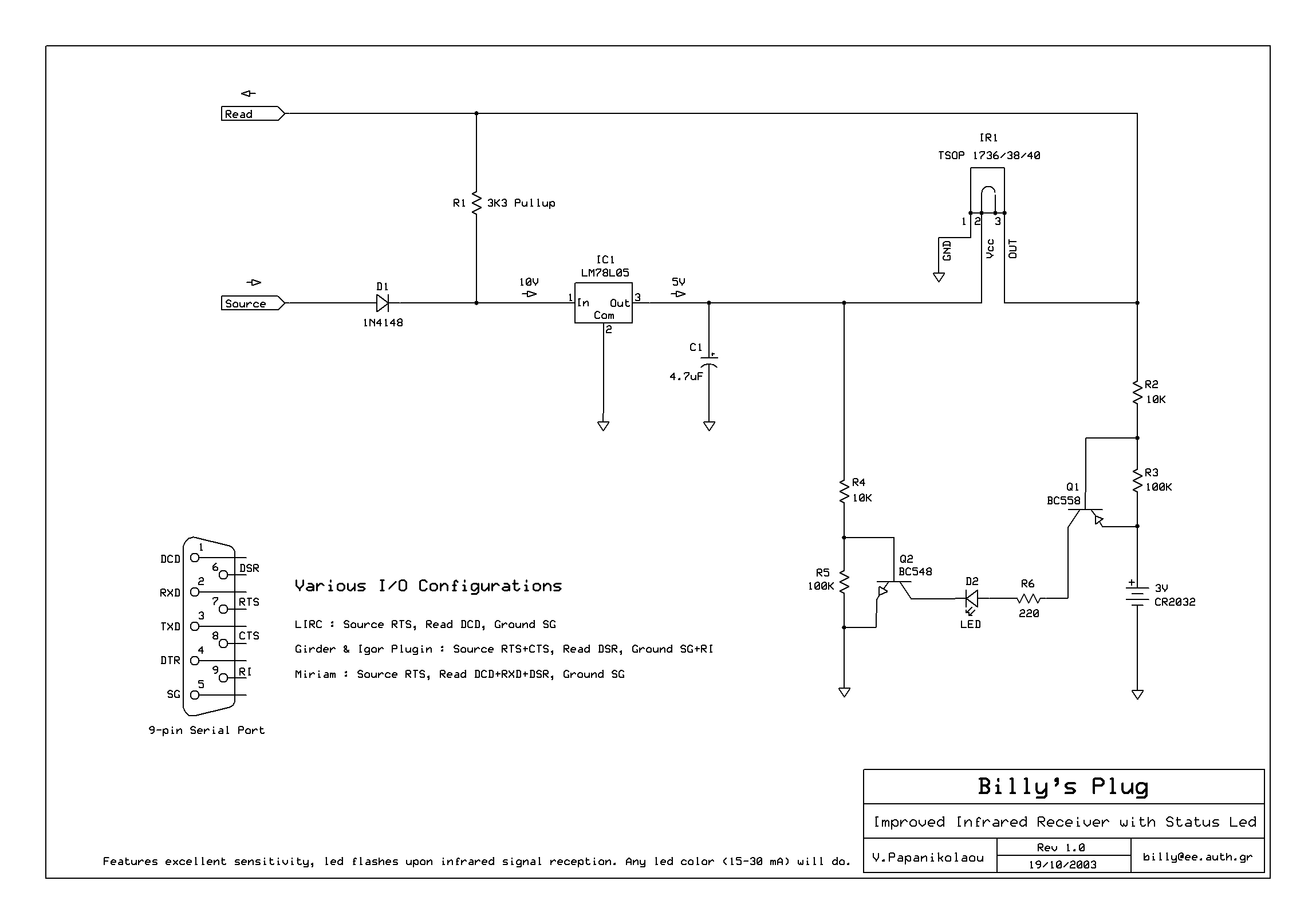
Serial port Infrared Receiver
This is a general purpose serial port infrared receiver. With the help of appropriate software, you can control different functions of your PC from a distance. For example, you can control your home cinema settings (volume, play, pause, stop, etc.),...
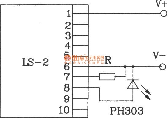
Direct infrared remote control switch circuit diagram composed of LS-2
The LS-2 remote control switch infrared sensor module is similar to the LS-18 but functions as a reflector. The LS-2 pin diagram and internal block diagram provide insights into its electrical parameters. The operating voltage for the LS-2 remote control...
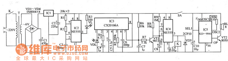
Infrared burglar alarm circuit schematic
The schematic for an infrared burglar alarm circuit is depicted in Figure 1. The infrared transmitter operates as a multivibrator with an oscillation frequency of 40 kHz, utilizing the NE555 integrated circuit (IC2), along with resistors R1 and R2 and...
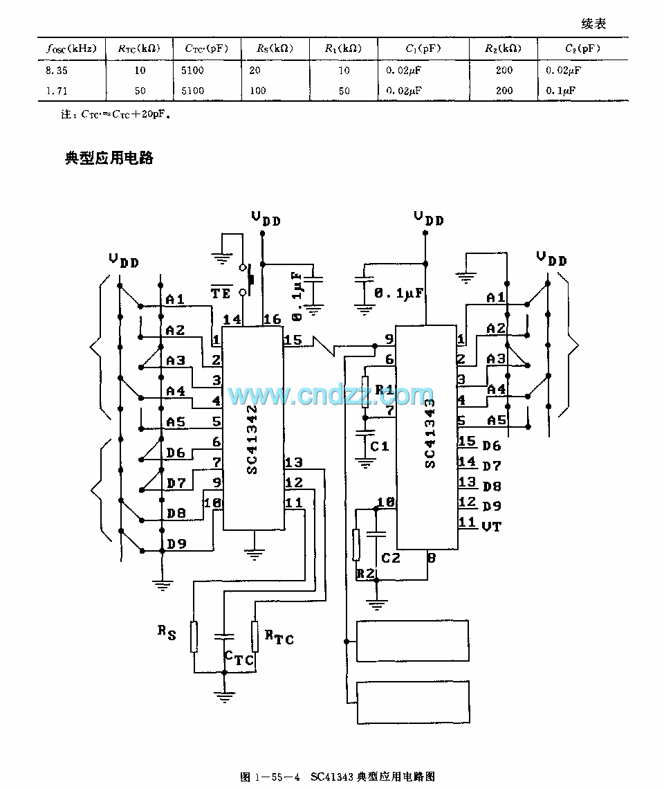
SC41343 general infrared ultrasonic or RF remote control launch coding circuit
The SC41343 is designed as a type of infrared, ultrasonic, or RF remote control launch coding circuit. The internal circuit comprises a sequence generator, control logic circuit, 4-bit shift register, data extraction circuit, and latch circuit. Features include the use...
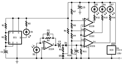
car parking sensor circuit using infra
All distances mentioned can vary depending on the infrared transmitting and receiving LEDs used and are significantly affected by the color of the reflecting surface. Black surfaces greatly reduce the device's sensitivity. This circuit can also be applied in various...
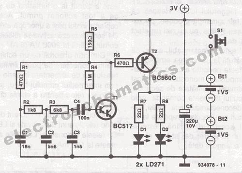
Basic Infrared IR Transmitter Circuit
This infrared transmitter is designed for use with an infrared receiver. It operates using either two 1.5V batteries or a 3V lithium battery, allowing for a compact infrared communication system.
The infrared transmitter circuit typically consists of an infrared LED, a...
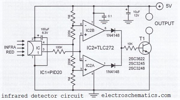
Infrared Detector Circuit with PID20
This infrared detector circuit utilizes a passive infrared detector component, PID20, which converts heat radiation into electrical impulses. The output voltage of the PID20 increases when an object approaches, provided that the object is warmer than the surrounding environment. The...
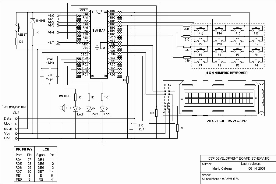
USB PICKit2 programmer
A schematic of a board featuring the PIC16F84 microcontroller, along with other compatible PIC microcontrollers that can be connected to the USB PICKit2 programmer. Additionally, there are concerns regarding the potential damage to the programmer when experimenting with oscillator frequencies...
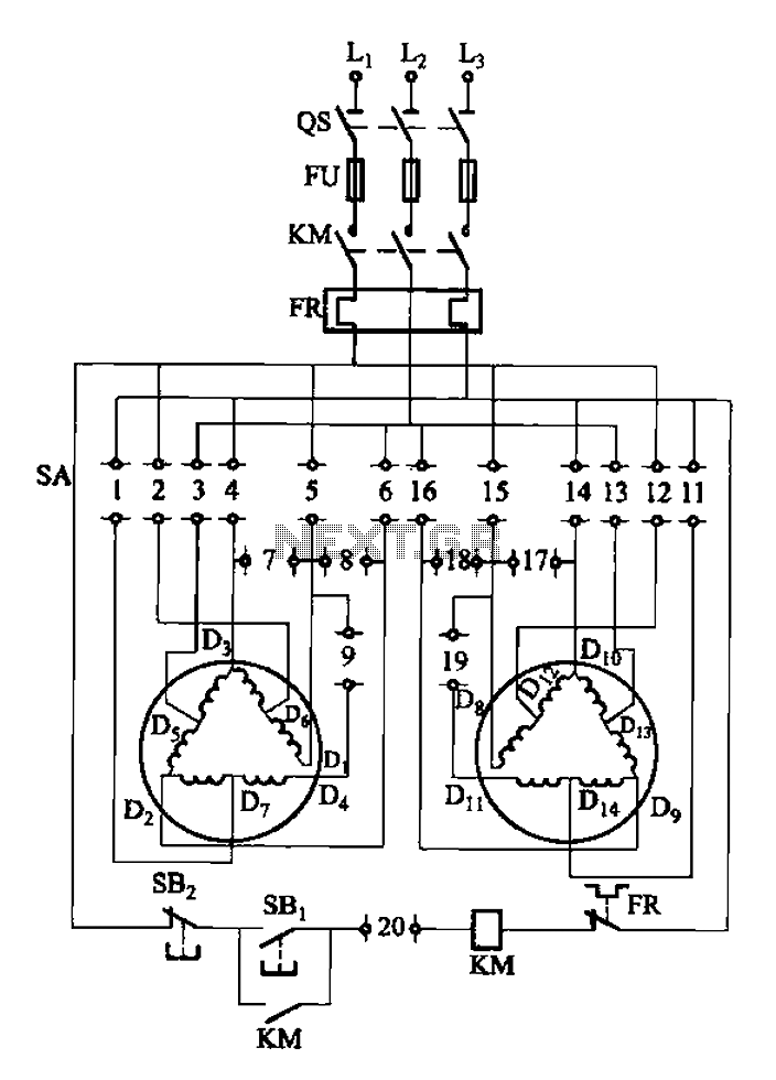
2Y-Y-2 - connection four-speed motor switch control circuit
The 3-119 circuit shown in the figure combines switch SA to realize the stator windings, specifically the 2, Y, and 2Y connections, which correspond to the motor speed n1.
The 3-119 circuit is designed to facilitate the control of motor speed...