


Casio cable for PC
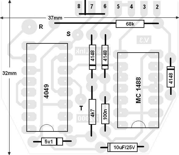
Description: Clean the surface to be glued components to the printed circuit. Use a sheet of very fine sandpaper to smooth bumps fortunes. First attach the resistors and diodes. Pay attention to the polarity of the diodes! Then glue the two finished watching the first position of the pin. Finally you can glue the two capacitors paying attention to the polarity of the electrolytic capacitor. Before sticking the electrolytic capacitor to the printed circuit glue the two contacts of two small extensions cable length of about 2cm. Then glue the edges of the extension to the printed always watching the polarity. In this way the capacitor is free from the printed and you can remove it from the position of the printed glue and mount the left of the IC 4049 where there is little space by adding a little glue. Check the photo below. This is to be closed box in which to place the circuit. To assemble the two parts of the printed slide between the two sets of pin to DB25 port! The adhesion of the printed surface should be "seen" on the side of the pin 1-13 and part of the materials you need to "see" the pin 14-25. Stick the pin through the printed starting with the pin number 2. You should also stick a bridge cable (wire link) next to the pins of the door. Refer to the diagram above material to accurately position the bridge is horizontal and connects the positions 8 and 6 printed. This should be glued stuck before the DB25. Stick to the side of the material. Then chrisimopoieisthe another small piece of cable to connect the first bridge to pin 20 of the door (NOT the pin 7, looking from the side of the material!). This is the vertical bridge shown in the diagram of the material starting from the middle of 8 and 7 and should lead to pin 20 of DB25. And it will stick by the side of the printed material, because that side will find the pin 20. You can stop the neighboring pin from the pin 20 upon touch to any party wire material to prevent the possibility of a short circuit when they are not used. Using the diagram of the material stick the tip of the wire corresponding to S in the position S printed the end of the cable corresponding to the R stick it to the R position of the printed and finally the end of the cable corresponding to T stick it in position T the printed. Xanaelenxte all stick and with a multimeter if you really elenxte T of connector plug in the T of the printed circuit board, do the same for other contacts. Before installing the construction of the housing will need to modify a little pouch that you bought. You should cut with a cutter plastic protrusions that exist in the inner sides of both sides of the housing through which normally spend the screws and any other feature would prevent the placement of printed. This results in a modified housing internally as the photo.
Resistor 4.7 kOhm (yellow-purple-red)
Resistor 68 KO (blue-gray-orange)
Electrolytic capacitor 10mF/25V
Capacitor 100nF
Diode 1N4148 (3 pieces)
Zener diode ZD 5n1
IC 4049
IC MC1488 or
Mechanical Materials
Cable and two blentaz 1,25 m similar to the headphone cable
2,5 mm plug (pin), stereo. (Must be very slim)
25pin female port
Case 25pin door with screws
The assembly process begins with the preparation of the printed circuit board (PCB), which involves cleaning the surface to ensure proper adhesion of components. Fine sandpaper is recommended for smoothing any irregularities. The initial placement of components includes resistors and diodes, with careful attention to the polarity of the diodes, as incorrect orientation can lead to circuit malfunction.
Following the placement of resistors and diodes, the two capacitors are attached, ensuring that the polarity of the electrolytic capacitor is respected. Two small extension cables, approximately 2 cm in length, are glued to the PCB before the capacitor is secured, allowing for easier removal and repositioning of the capacitor adjacent to the IC 4049, which is crucial for space management on the PCB.
The integration of the DB25 connector involves sliding the two parts of the printed circuit together, aligning the pins correctly. The assembly requires that the printed surface be oriented such that specific pins (1-13) are visible while ensuring that the necessary connections to pins 14-25 are made. The connection process starts with pin number 2, continuing with the attachment of a bridge cable that connects printed positions 8 and 6 as indicated in the schematic.
A vertical bridge is also established from the middle of pins 8 and 7 to pin 20 of the DB25 connector, ensuring that the wiring is secured to prevent short circuits. Each connection is verified using a multimeter to confirm continuity and correct placement.
Before finalizing the assembly, the housing must be modified to accommodate the PCB. This involves cutting away plastic protrusions that could obstruct the placement of the printed circuit board, ensuring a clean and secure fit within the case. The final assembly results in a compact and functional electronic device, adhering to the specified design and layout requirements.Clean the surface to be glued components to the printed circuit. Use a sheet of very fine sandpaper to smooth bumps fortunes. First attach the resistors and diodes. Pay attention to the polarity of the diodes! Then glue the two finished watching the first position of the pin. Finally you can glue the two capacitors paying attention to the polarity of the electrolytic capacitor. Before sticking the electrolytic capacitor to the printed circuit glue the two contacts of two small extensions cable length of about 2cm.
Then glue the edges of the extension to the printed always watching the polarity. In this way the capacitor is free from the printed and you can remove it from the position of the printed glue and mount the left of the IC 4049 where there is little space by adding a little glue. Check the photo below. This is to be closed box in which to place the circuit. To assemble the two parts of the printed slide between the two sets of pin to DB25 port! The adhesion of the printed surface should be "seen" on the side of the pin 1-13 and part of the materials you need to "see" the pin 14-25. Stick the pin through the printed starting with the pin number 2. You should also stick a bridge cable (wire link) next to the pins of the door. Refer to the diagram above material to accurately position the bridge is horizontal and connects the positions 8 and 6 printed.
This should be glued stuck before the DB25. Stick to the side of the material. Then chrisimopoieisthe another small piece of cable to connect the first bridge to pin 20 of the door (NOT the pin 7, looking from the side of the material!). This is the vertical bridge shown in the diagram of the material starting from the middle of 8 and 7 and should lead to pin 20 of DB25.
And it will stick by the side of the printed material, because that side will find the pin 20. You can stop the neighboring pin from the pin 20 upon touch to any party wire material to prevent the possibility of a short circuit when they are not used. Using the diagram of the material stick the tip of the wire corresponding to S in the position S printed the end of the cable corresponding to the R stick it to the R position of the printed and finally the end of the cable corresponding to T stick it in position T the printed.
Xanaelenxte all stick and with a multimeter if you really elenxte T of connector plug in the T of the printed circuit board, do the same for other contacts. Before installing the construction of the housing will need to modify a little pouch that you bought.
You should cut with a cutter plastic protrusions that exist in the inner sides of both sides of the housing through which normally spend the screws and any other feature would prevent the placement of printed. This results in a modified housing internally as the photo. Resistor 4.7 kOhm (yellow-purple-red) · Resistor 68 KO (blue-gray-orange) · Electrolytic capacitor 10mF/25V · Capacitor 100nF · Diode 1N4148 (3 pieces) · Zener diode ZD 5n1 · IC 4049 · IC MC1488 or Mechanical Materials · Cable and two blentaz 1,25 m similar to the headphone cable · 2,5 mm plug (pin), stereo.
(Must be very slim) · 25pin female port · Case 25pin door with screws
Resistor 4.7 kOhm (yellow-purple-red)
Resistor 68 KO (blue-gray-orange)
Electrolytic capacitor 10mF/25V
Capacitor 100nF
Diode 1N4148 (3 pieces)
Zener diode ZD 5n1
IC 4049
IC MC1488 or
Mechanical Materials
Cable and two blentaz 1,25 m similar to the headphone cable
2,5 mm plug (pin), stereo. (Must be very slim)
25pin female port
Case 25pin door with screws
The assembly process begins with the preparation of the printed circuit board (PCB), which involves cleaning the surface to ensure proper adhesion of components. Fine sandpaper is recommended for smoothing any irregularities. The initial placement of components includes resistors and diodes, with careful attention to the polarity of the diodes, as incorrect orientation can lead to circuit malfunction.
Following the placement of resistors and diodes, the two capacitors are attached, ensuring that the polarity of the electrolytic capacitor is respected. Two small extension cables, approximately 2 cm in length, are glued to the PCB before the capacitor is secured, allowing for easier removal and repositioning of the capacitor adjacent to the IC 4049, which is crucial for space management on the PCB.
The integration of the DB25 connector involves sliding the two parts of the printed circuit together, aligning the pins correctly. The assembly requires that the printed surface be oriented such that specific pins (1-13) are visible while ensuring that the necessary connections to pins 14-25 are made. The connection process starts with pin number 2, continuing with the attachment of a bridge cable that connects printed positions 8 and 6 as indicated in the schematic.
A vertical bridge is also established from the middle of pins 8 and 7 to pin 20 of the DB25 connector, ensuring that the wiring is secured to prevent short circuits. Each connection is verified using a multimeter to confirm continuity and correct placement.
Before finalizing the assembly, the housing must be modified to accommodate the PCB. This involves cutting away plastic protrusions that could obstruct the placement of the printed circuit board, ensuring a clean and secure fit within the case. The final assembly results in a compact and functional electronic device, adhering to the specified design and layout requirements.Clean the surface to be glued components to the printed circuit. Use a sheet of very fine sandpaper to smooth bumps fortunes. First attach the resistors and diodes. Pay attention to the polarity of the diodes! Then glue the two finished watching the first position of the pin. Finally you can glue the two capacitors paying attention to the polarity of the electrolytic capacitor. Before sticking the electrolytic capacitor to the printed circuit glue the two contacts of two small extensions cable length of about 2cm.
Then glue the edges of the extension to the printed always watching the polarity. In this way the capacitor is free from the printed and you can remove it from the position of the printed glue and mount the left of the IC 4049 where there is little space by adding a little glue. Check the photo below. This is to be closed box in which to place the circuit. To assemble the two parts of the printed slide between the two sets of pin to DB25 port! The adhesion of the printed surface should be "seen" on the side of the pin 1-13 and part of the materials you need to "see" the pin 14-25. Stick the pin through the printed starting with the pin number 2. You should also stick a bridge cable (wire link) next to the pins of the door. Refer to the diagram above material to accurately position the bridge is horizontal and connects the positions 8 and 6 printed.
This should be glued stuck before the DB25. Stick to the side of the material. Then chrisimopoieisthe another small piece of cable to connect the first bridge to pin 20 of the door (NOT the pin 7, looking from the side of the material!). This is the vertical bridge shown in the diagram of the material starting from the middle of 8 and 7 and should lead to pin 20 of DB25.
And it will stick by the side of the printed material, because that side will find the pin 20. You can stop the neighboring pin from the pin 20 upon touch to any party wire material to prevent the possibility of a short circuit when they are not used. Using the diagram of the material stick the tip of the wire corresponding to S in the position S printed the end of the cable corresponding to the R stick it to the R position of the printed and finally the end of the cable corresponding to T stick it in position T the printed.
Xanaelenxte all stick and with a multimeter if you really elenxte T of connector plug in the T of the printed circuit board, do the same for other contacts. Before installing the construction of the housing will need to modify a little pouch that you bought.
You should cut with a cutter plastic protrusions that exist in the inner sides of both sides of the housing through which normally spend the screws and any other feature would prevent the placement of printed. This results in a modified housing internally as the photo. Resistor 4.7 kOhm (yellow-purple-red) · Resistor 68 KO (blue-gray-orange) · Electrolytic capacitor 10mF/25V · Capacitor 100nF · Diode 1N4148 (3 pieces) · Zener diode ZD 5n1 · IC 4049 · IC MC1488 or Mechanical Materials · Cable and two blentaz 1,25 m similar to the headphone cable · 2,5 mm plug (pin), stereo.
(Must be very slim) · 25pin female port · Case 25pin door with screws
Automatic lighting control telephone signals
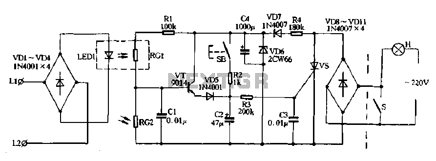
Diodes VD8 to VDI1 function as part of the main circuit isolation, with SCR serving as a composition control switch. The buck regulator circuit is composed of a stable orbital tube VD6 and a simple resistor-capacitor combination (C4). The circuit...
PC FM Radio Circuit
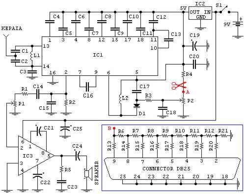
If familiar with programming languages such as C++, PASCAL, VISUAL BASIC, or DELPHI, it is possible to write a program that sends numbers from 0 to 255 through the parallel port (378 I) of a PC. This process checks the...
control interface via pc keyboard
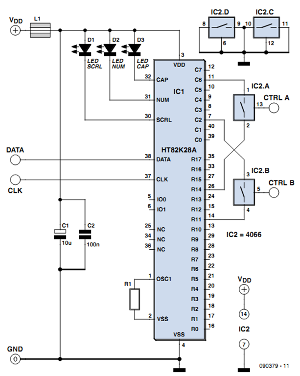
One of the more challenging aspects of creating a control or security system that utilizes a PC, such as a burglar alarm, is connecting the sensors to the computer. This typically requires specialized interface expansion boards, and programming that includes...
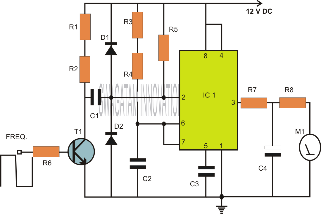
how to build inexpensive frequency
Capacitors are major electronic components classified as passive components. They are extensively used in electronic circuits, and virtually no circuit can be constructed without these essential parts. The primary function of a capacitor is to block direct current (DC) while...
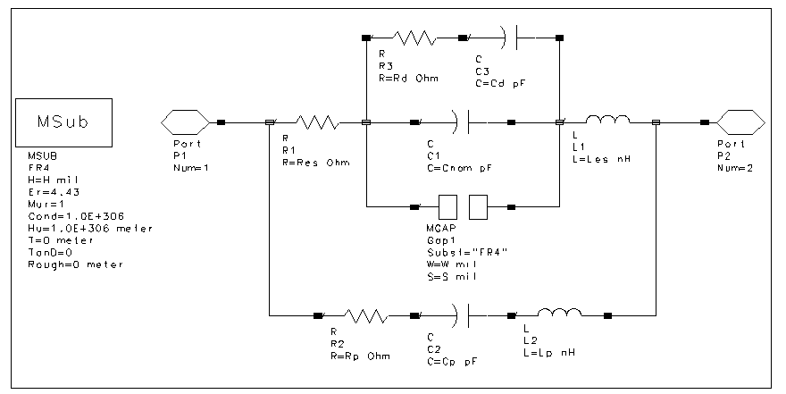
muRata Manufacturing Measurement-Based SMT Capacitors
The schematic design of the equivalent circuit model for Murata Manufacturing's measurement-based GRH series SMT capacitors is derived from device measurements and modeling conducted by Murata. This model is applicable to capacitors mounted on an FR4 substrate, with constant substrate...
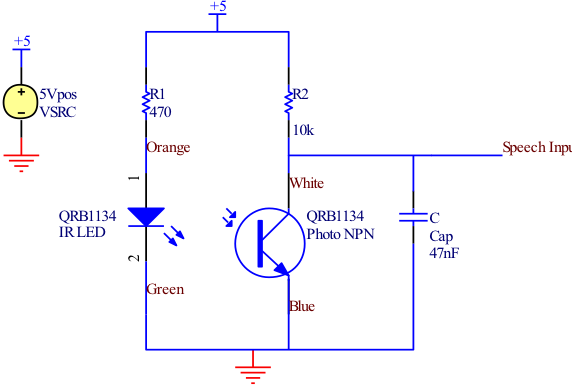
Circuit Schematics
All integrated circuits (ICs) are equipped with a 0.1 µF monolithic ceramic capacitor connected across their terminals. Additionally, each board features two capacitors: a 10 µF tantalum capacitor and a 100 µF electrolytic capacitor. The START BUTTON serves as a...
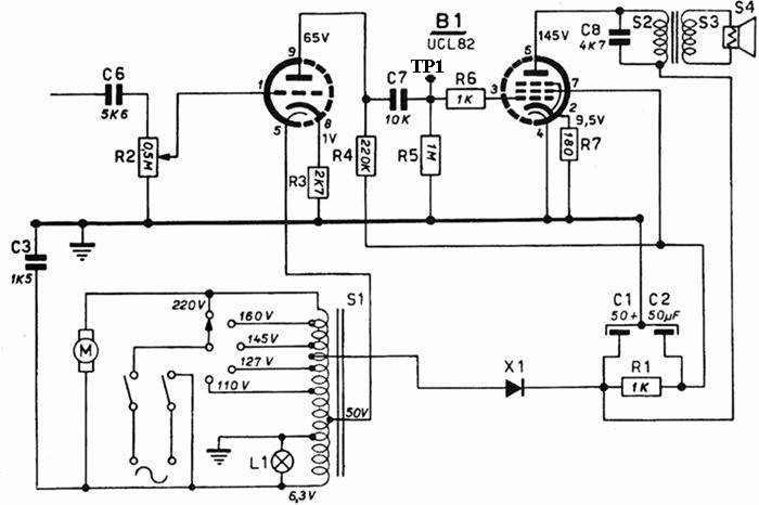
Replacing old capacitors
Original components, when still functional, exhibit stability and are not subject to infant mortality. Individual opinions may vary based on personal experiences. However, responses can differ due to several factors: the quality of the design utilizing appropriate components, the type...
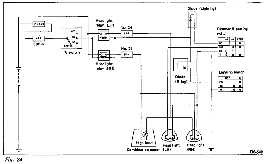
Whats the purpose of the diodes in this circuit
Understanding the headlight wiring in a car involves examining the purpose of two diodes in the circuit diagram. The circuit allows for two independent methods of activating the light relays: through the light switch or by flashing the high beams....
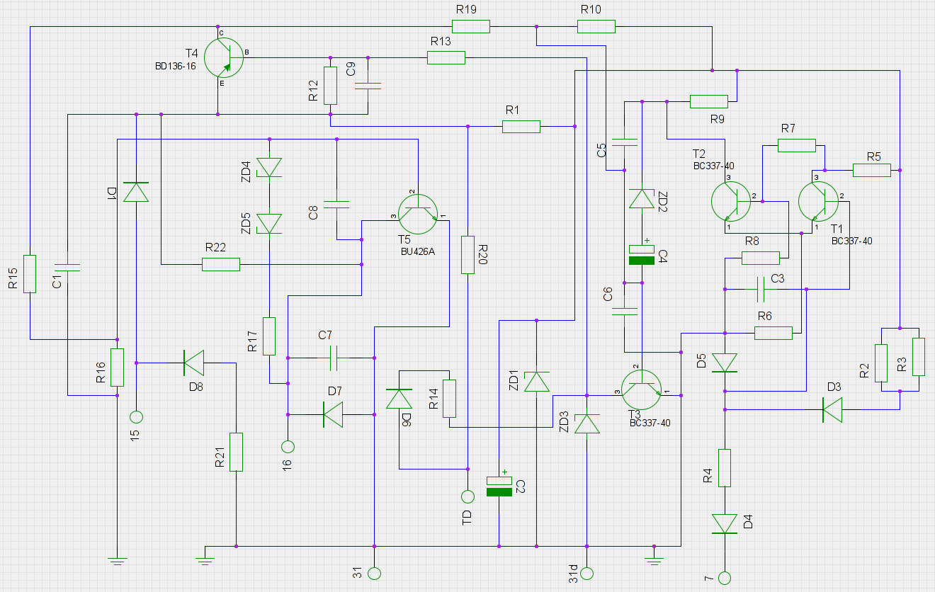
pcb Need help with identifying diodes in a 1970s automotive circuit
An old ignition module from a 1978 W116 model Mercedes-Benz is being reverse-engineered. The original circuit diagram is not available, so a new one has been created based on the printed circuit board (PCB). The circuit has been assessed to...