


CS37-2 machine tube feeding circuit diagram
#feeding tube
#filament voltage
#flyback transformer
#current limiting resistor
#color TV
#CS37-2
#circuit diagram
#swallow
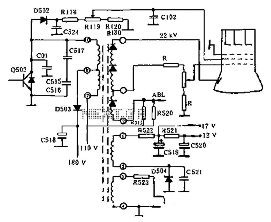
Description: The circuit diagram of the Swallow CS37-2 type color TV illustrates the feeding tube configuration. The filament voltage is supplied by the line flyback transformer, with a current-limiting resistor R523. The accelerating voltage is managed by D502, which rectifies the retrace negative peak pulse. After filtering through components R118, R119, R120, and R130, the partial voltage supplied by R119 allows for adjustment of the high voltage level. The focus voltage and anode voltage are generated by a multi-stage supply, with a tap on the primary winding. A resistor divider supplies the focus electrode. The focus trim resistors are enclosed within the transformer, with only a rotary handle accessible externally. The focus voltage is directly routed through a high-voltage lead to the CRT tube socket's focusing electrode terminals for improved closure. The anode voltage is supplied by the high voltage winding, connected to the suction tube cone sleeve via a high-voltage lead that features a round hat hook. The CRT beam current varies significantly with the content of the image, necessitating a high-voltage power adjustment feature to prevent amplitude variation in the grating and deterioration of focus and convergence. Consequently, some televisions incorporate a high voltage stabilization circuit.
The Swallow CS37-2 color television circuit operates with a focus on efficient voltage management and stability. The filament voltage generated by the flyback transformer is critical for the operation of the CRT, ensuring that the electron gun is adequately heated for optimal performance. The inclusion of the current-limiting resistor R523 is essential to protect the transformer and maintain consistent filament operation.
The accelerating voltage, rectified by diode D502, is pivotal in shaping the electron beam's intensity and direction. The filtering capacitors and resistors (R118, R119, R120, and R130) create a stable voltage supply, with R119 specifically allowing for fine-tuning of the high voltage output. This adjustability is crucial for achieving the desired brightness and contrast levels on the screen.
The focus voltage and anode voltage are generated through a multi-stage transformer winding, with a specific tap designated for focus voltage supply. The use of a resistor divider ensures that the focus electrode receives the correct voltage level, which is necessary for maintaining image sharpness. The focus trim resistors, sealed within the transformer, provide a means of calibration while ensuring that the settings are not easily tampered with.
The high-voltage lead connecting to the CRT socket is designed for reliability and safety, facilitating the transmission of high voltage to the focusing electrode. This connection is critical for maintaining the integrity of the electron beam as it travels towards the phosphor-coated screen.
As the content displayed on the CRT changes, the beam current fluctuates, which can affect the overall image quality. Therefore, the incorporation of a high-voltage power adjustment feature is vital to ensure consistent performance. This adjustment helps mitigate issues such as grating amplitude variations and degradation in focus and convergence, which can lead to a poor viewing experience. The addition of a high voltage stabilization circuit further enhances the reliability of the television's operation, ensuring that voltage levels remain consistent under varying operational conditions. This comprehensive approach to circuit design underscores the complexity and precision required in modern television technology. As shown in the circuit diagram of the feeding tube Swallow CS37-2 type color TV. Filament voltage by the line flyback transformer, winding current limiting resistor R523 is su pplied. Accelerating voltage by D502 to retrace negative peak pulse rectifier, the C524 after filtering by the R118, R119, R120, R130 partial pressure after supplying section R119 can adjust the size of the high voltage. Focus voltage and anode voltage boost primary winding of the multi-stage supply, which one-third of the tap, after the resistor divider supplying focus electrode.
Focus trim resistors are sealed inside the transformer, only to reveal a rotary handle outside. Focus voltage generated by a high-voltage lead lead directly to the CRT tube socket focusing electrode terminals and closed better. Anode voltage supplied by the high voltage winding of all, hang in the suction tube cone sleeve high pressure by the high-voltage lead at the mouth with a round hat hook.
CRT beam current is greatly with picture content changes, and called for high-voltage power adjustment feature is better, otherwise it will cause the grating amplitude variation, focus and convergence deteriorates. For this reason, some TV plus high voltage stabilization circuit.
The Swallow CS37-2 color television circuit operates with a focus on efficient voltage management and stability. The filament voltage generated by the flyback transformer is critical for the operation of the CRT, ensuring that the electron gun is adequately heated for optimal performance. The inclusion of the current-limiting resistor R523 is essential to protect the transformer and maintain consistent filament operation.
The accelerating voltage, rectified by diode D502, is pivotal in shaping the electron beam's intensity and direction. The filtering capacitors and resistors (R118, R119, R120, and R130) create a stable voltage supply, with R119 specifically allowing for fine-tuning of the high voltage output. This adjustability is crucial for achieving the desired brightness and contrast levels on the screen.
The focus voltage and anode voltage are generated through a multi-stage transformer winding, with a specific tap designated for focus voltage supply. The use of a resistor divider ensures that the focus electrode receives the correct voltage level, which is necessary for maintaining image sharpness. The focus trim resistors, sealed within the transformer, provide a means of calibration while ensuring that the settings are not easily tampered with.
The high-voltage lead connecting to the CRT socket is designed for reliability and safety, facilitating the transmission of high voltage to the focusing electrode. This connection is critical for maintaining the integrity of the electron beam as it travels towards the phosphor-coated screen.
As the content displayed on the CRT changes, the beam current fluctuates, which can affect the overall image quality. Therefore, the incorporation of a high-voltage power adjustment feature is vital to ensure consistent performance. This adjustment helps mitigate issues such as grating amplitude variations and degradation in focus and convergence, which can lead to a poor viewing experience. The addition of a high voltage stabilization circuit further enhances the reliability of the television's operation, ensuring that voltage levels remain consistent under varying operational conditions. This comprehensive approach to circuit design underscores the complexity and precision required in modern television technology. As shown in the circuit diagram of the feeding tube Swallow CS37-2 type color TV. Filament voltage by the line flyback transformer, winding current limiting resistor R523 is su pplied. Accelerating voltage by D502 to retrace negative peak pulse rectifier, the C524 after filtering by the R118, R119, R120, R130 partial pressure after supplying section R119 can adjust the size of the high voltage. Focus voltage and anode voltage boost primary winding of the multi-stage supply, which one-third of the tap, after the resistor divider supplying focus electrode.
Focus trim resistors are sealed inside the transformer, only to reveal a rotary handle outside. Focus voltage generated by a high-voltage lead lead directly to the CRT tube socket focusing electrode terminals and closed better. Anode voltage supplied by the high voltage winding of all, hang in the suction tube cone sleeve high pressure by the high-voltage lead at the mouth with a round hat hook.
CRT beam current is greatly with picture content changes, and called for high-voltage power adjustment feature is better, otherwise it will cause the grating amplitude variation, focus and convergence deteriorates. For this reason, some TV plus high voltage stabilization circuit.
Flyback Transformer Drivers
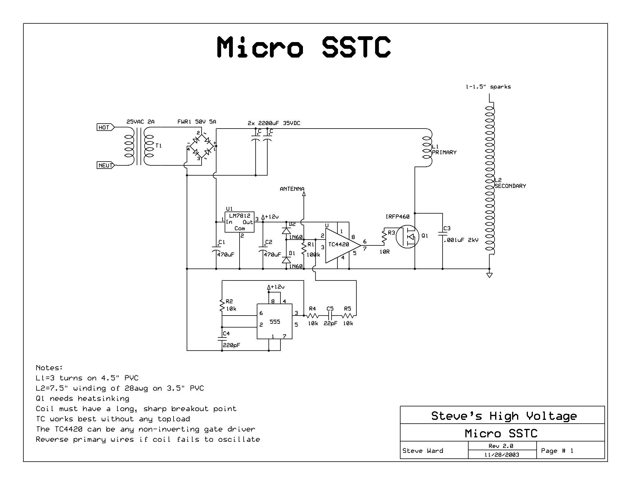
A solid-state flyback driver based on a micro solid-state Tesla coil circuit created by Steve Ward. The schematic is reprinted here with credits to Steve Ward. Instead of an air-core Tesla Coil setup, a flyback transformer is utilized. An IRFP450...
Flyback Transformer Drivers
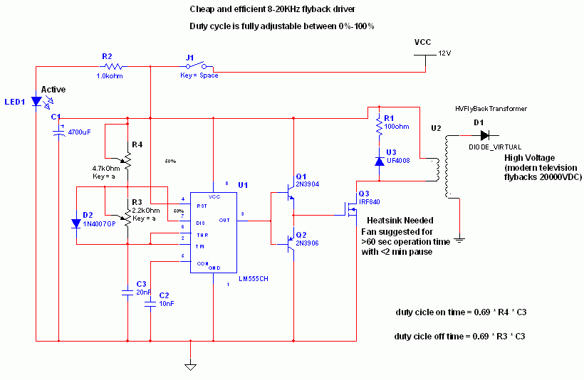
This is an efficient flyback driver for modern cylindrical rectified television flybacks. Many sites do not provide circuits for driving these transformers; they simply state that they are ineffective. However, this circuit has been built and tested, focusing on finding...
half bridge flyback driver
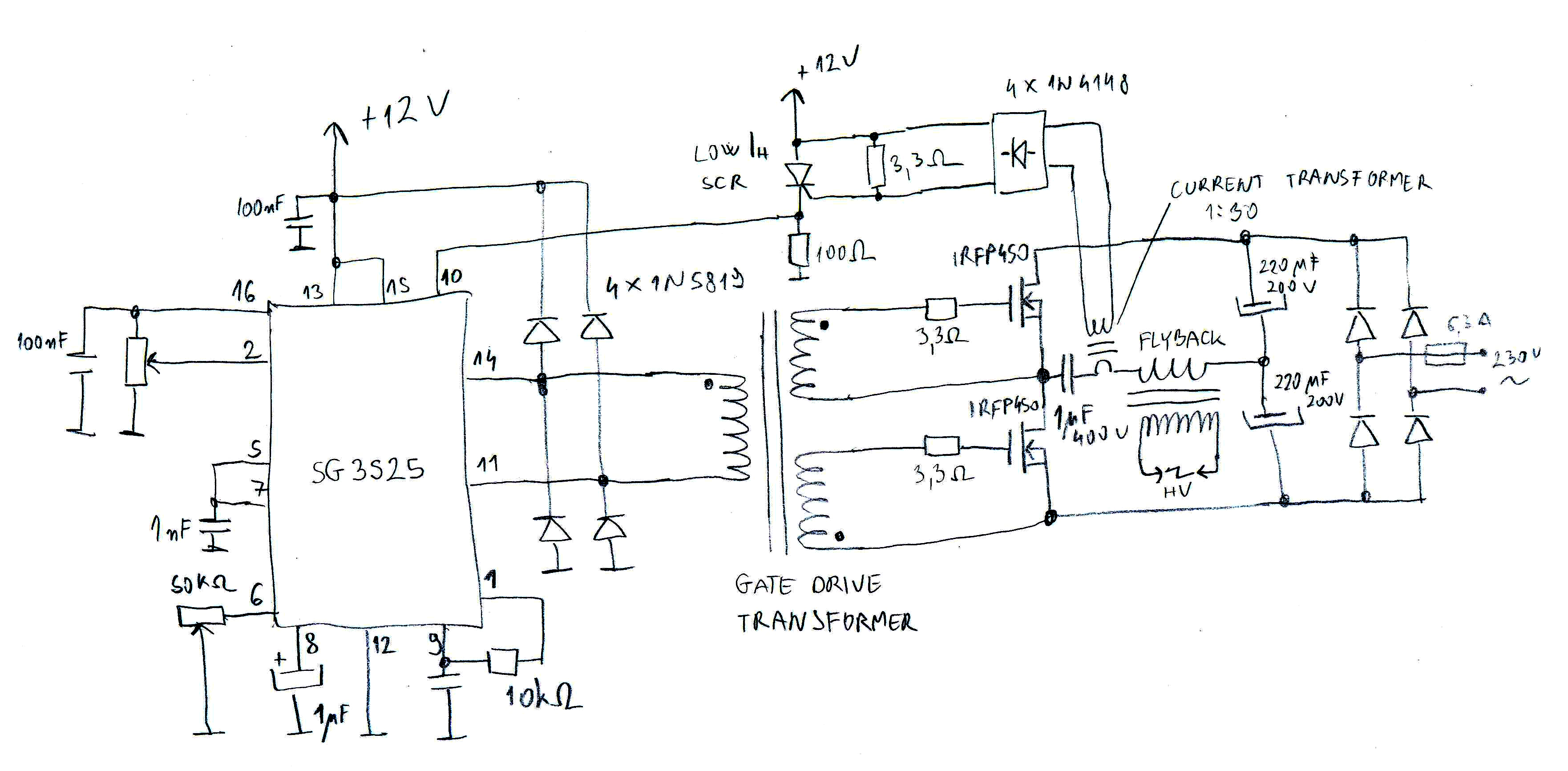
A flyback driver is a common high-voltage generator used by amateurs. It consists of a cathode-ray tube (CRT) TV high-voltage transformer driven by a high-frequency inverter to obtain a high-voltage output. The initial and simplest driver designs typically featured a...
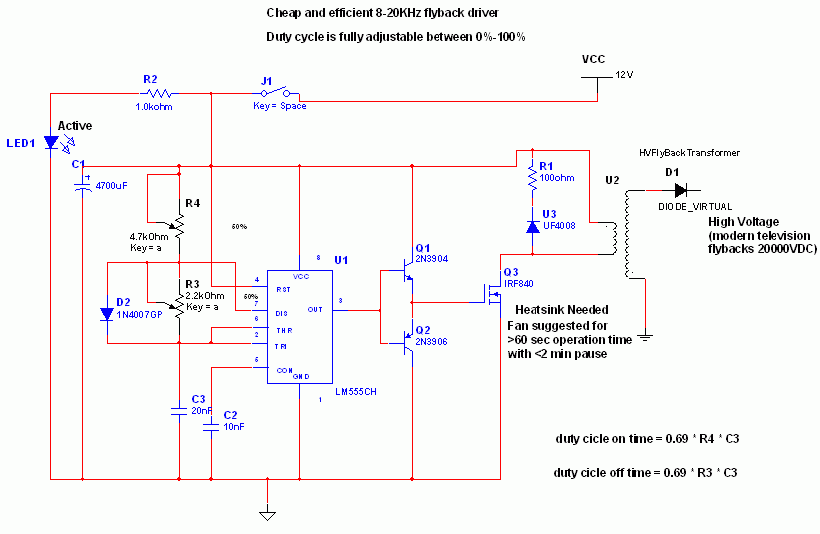
Flyback Transformer Driver Circuit
Many sites do not provide circuits for driving these transformers; they simply state that they are ineffective. However, this assertion is contested. A circuit has been developed that operates effectively, with significant effort invested in determining the resonant frequency (approximately...
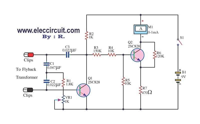
Flyback transformer tester circuit using 2SC828
The circuit tests a flyback transformer used in televisions, and it is simple, easy, and inexpensive to construct. A friend who is a TV repairman provided this information.
The circuit designed for testing a flyback transformer is essential for diagnosing issues...
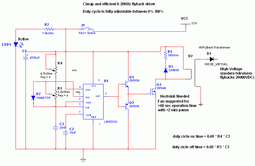
Flyback Transformer Driver
An efficient flyback driver for modern cylindrical rectified television flybacks. Many sources do not provide circuits for driving these transformers, often deeming them ineffective. However, this circuit has been successfully constructed. Significant effort was dedicated to determining the resonant frequency...
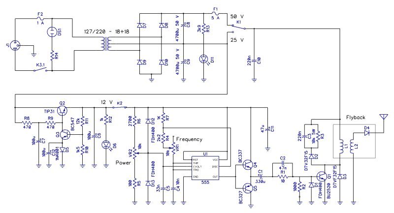
Experiments with flybacks
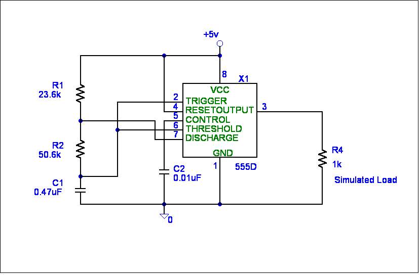
The initial design utilized a small flyback transformer from an old computer, paired with a simple driver circuit based on a 555 integrated circuit (IC). This circuit featured AC coupling to the driver transistor and was assembled on a perforated...
Designing your own gear
Flyback transformers are commonly used in television sets and can generate up to 50,000 volts, which is sufficient to lift a 350-pound individual and throw them back 10 to 20 feet, potentially causing fatal injuries. The components are sensitive to...
High Power Full Bridge Flyback Driver circuit
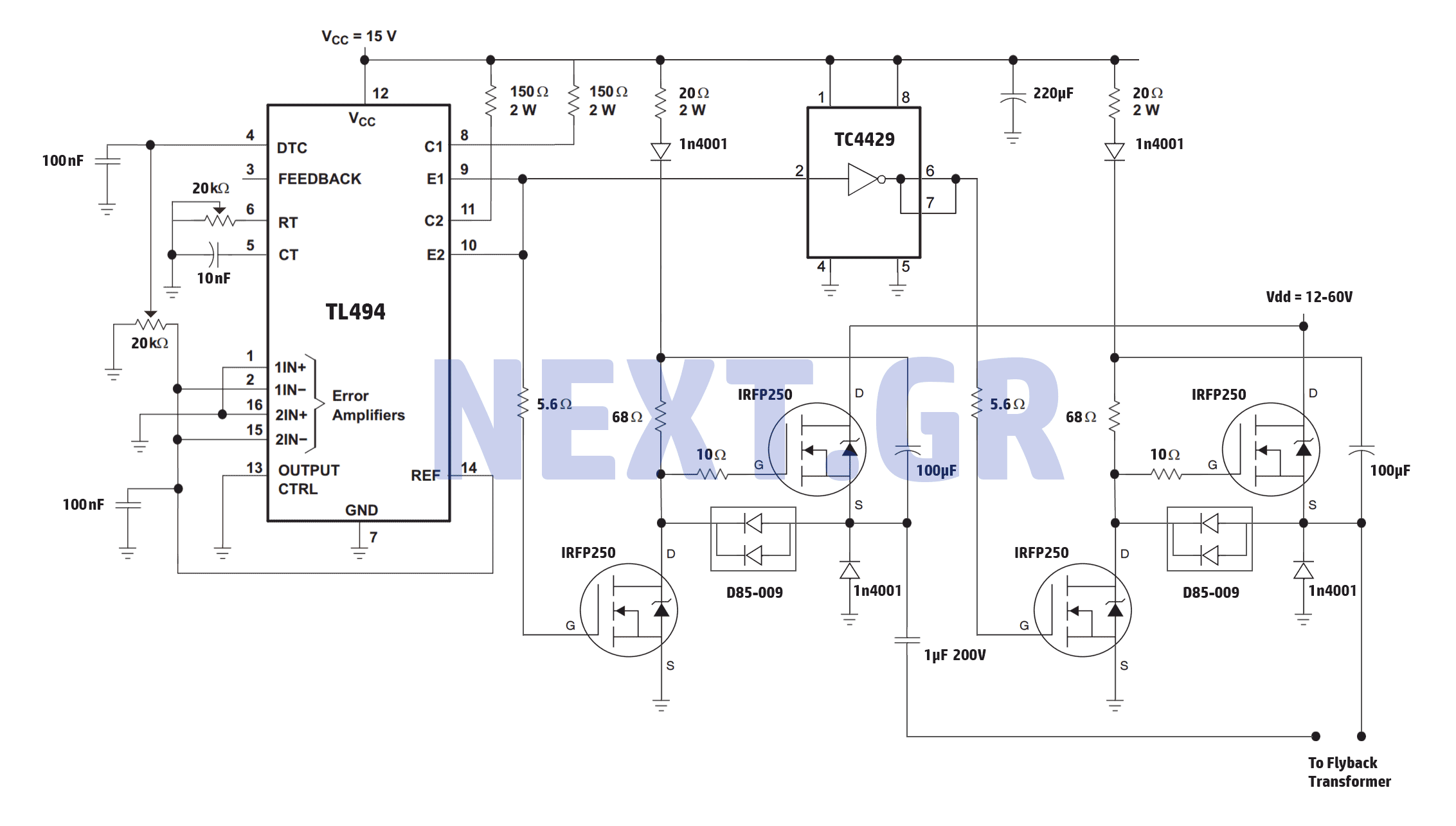
A reliable full bridge driver is essential for driving a flyback transformer. While many flyback driver schematics exist, most lack durability. The well-known Zero Voltage Switching (ZVS) driver, invented by Vladmiro Mazilli, is recognized for its reliability due to its...