


sleeping aid schematics
#sleep aid
#magnetic field
#biohacking
#relaxation
#brain waves
#natural surroundings
#health
#wellness
#sensor
#low frequency
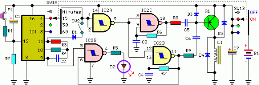
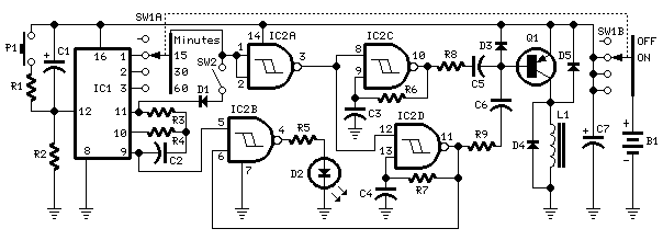
Description: Many individuals find that they sleep well in natural environments, such as tents or wooden huts. This phenomenon is attributed not only to the healthy surroundings but also to our subconscious ability to perceive the Earth's natural magnetic fields. The circuit designed generates these types of geo-magnetic fields, allowing users to sense them, thereby creating an optimal environment for restful sleep. The foundational concepts for this circuit originate from German research. Integrated circuits IC2C and IC2D produce two square wave signals at approximately 1.2 Hz and 5 Hz, respectively. These waveforms are transformed into 60 µs pulses at the same frequencies using capacitors C5 and C6, which are then mixed at the base of transistor Q1. This transistor drives a radiator coil with a series of scalar pulses, each 60 µs in duration and with an amplitude of 9V. The timer section is composed of IC1, IC2A, and IC2B. Capacitor C1 and resistor R2 facilitate the auto-reset of IC1 upon power-up. The internal oscillator of IC1 operates a 14-stage ripple counter, which, after roughly 15 minutes, causes output pin 1 to go high. Consequently, pin 3 of IC2A goes low, halting the oscillations of IC2C and IC2D. If switch SW2 is left open (Alternate mode operation), after 15 minutes, pin 1 of IC1 goes low, pin 3 of IC2A goes high, and the oscillators are re-enabled. Conversely, if SW2 is closed (Stop mode operation), the first time output pin 1 of IC1 goes high, the internal oscillator of the IC is disabled via diode D1. As a result, the circuit remains inactive until a reset pulse is applied to pin 12 through potentiometer P1 or when the device is completely powered off and restarted. A similar process occurs when switch SW1 is set to the 30 or 60-minute positions, effectively altering the duration of operation.
The circuit operates by utilizing two integrated circuits, IC2C and IC2D, which generate low-frequency square waves. These frequencies are critical as they mimic natural geo-magnetic fields, facilitating a calming effect conducive to sleep. The mixing of these signals at the base of transistor Q1 ensures that the desired pulse characteristics are maintained, providing a consistent output to the radiator coil.
The timer section, featuring IC1, IC2A, and IC2B, plays a pivotal role in managing the operational timing of the circuit. The auto-reset function provided by C1 and R2 ensures that the circuit initializes correctly upon power-up, preventing any unintended behavior. The 14-stage ripple counter integrated into IC1 is responsible for tracking the passage of time, with specific outputs controlling the oscillators' states.
The design incorporates a dual operational mode, allowing users to select between continuous operation or a timed shutdown. The use of switch SW2 for mode selection enhances user control, while the inclusion of diode D1 prevents the oscillator from retriggering until a reset condition is met. This design consideration ensures that the appliance can be safely powered down without losing its settings.
Overall, the circuit is an innovative approach to replicating the natural magnetic environment that promotes better sleep, leveraging simple electronic components to achieve a complex physiological effect. The careful consideration of timing, signal generation, and user control makes this circuit a valuable tool for enhancing sleep quality through the emulation of natural conditions.Many people experienced sleeping well in natural surroundings, into a tent or a wooden hut. This fact is due not only to the healthy atmosphere but also from our unconscious ability to perceive natural Earth`s magnetic-fields. The circuit generates this type of Geo-magnetic-fields and lets us perceive them: in this manner our brain is surrounded b
y an ideal environment for a sound sleep. (N. B. Basic ideas for this circuit are coming from German papers). IC2C and IC2D generate two square waves at about 1. 2 and 5 Hz respectively. These wave-forms are converted into 60 µS pulses at the same frequencies by means of C5 & C6 and mixed at Q1 Base. This transistor drives the Radiator coil with a scalar series of pulses of 60 µS length and 9V amplitude.
IC1, IC2A & IC2B form the timer section. C1 & R2 provide auto-reset of IC1 at switch-on. The internal oscillator of IC1 drives the 14 stage ripple counter and, after about 15 minutes, output pin 1 goes high. Pin 3 of IC2A goes low and stops IC2C & IC2D oscillation. If SW2 is left open (Alternate mode operation), after 15 minutes pin 1 of IC1 goes low, pin 3 of IC2A goes high and oscillators are enabled again.
If SW2 is closed (Stop mode operation), the first time output pin 1 of IC1 goes high, the internal oscillator of the IC is disabled by means of D1. Therefore the circuit remains off until a reset pulse is applied to pin 12 by means of P1 or when the whole device is switched-off and then restarted.
The same thing occurs when SW1 is switched on 30 or 60 minutes positions, obviously changing time length.
The circuit operates by utilizing two integrated circuits, IC2C and IC2D, which generate low-frequency square waves. These frequencies are critical as they mimic natural geo-magnetic fields, facilitating a calming effect conducive to sleep. The mixing of these signals at the base of transistor Q1 ensures that the desired pulse characteristics are maintained, providing a consistent output to the radiator coil.
The timer section, featuring IC1, IC2A, and IC2B, plays a pivotal role in managing the operational timing of the circuit. The auto-reset function provided by C1 and R2 ensures that the circuit initializes correctly upon power-up, preventing any unintended behavior. The 14-stage ripple counter integrated into IC1 is responsible for tracking the passage of time, with specific outputs controlling the oscillators' states.
The design incorporates a dual operational mode, allowing users to select between continuous operation or a timed shutdown. The use of switch SW2 for mode selection enhances user control, while the inclusion of diode D1 prevents the oscillator from retriggering until a reset condition is met. This design consideration ensures that the appliance can be safely powered down without losing its settings.
Overall, the circuit is an innovative approach to replicating the natural magnetic environment that promotes better sleep, leveraging simple electronic components to achieve a complex physiological effect. The careful consideration of timing, signal generation, and user control makes this circuit a valuable tool for enhancing sleep quality through the emulation of natural conditions.Many people experienced sleeping well in natural surroundings, into a tent or a wooden hut. This fact is due not only to the healthy atmosphere but also from our unconscious ability to perceive natural Earth`s magnetic-fields. The circuit generates this type of Geo-magnetic-fields and lets us perceive them: in this manner our brain is surrounded b
y an ideal environment for a sound sleep. (N. B. Basic ideas for this circuit are coming from German papers). IC2C and IC2D generate two square waves at about 1. 2 and 5 Hz respectively. These wave-forms are converted into 60 µS pulses at the same frequencies by means of C5 & C6 and mixed at Q1 Base. This transistor drives the Radiator coil with a scalar series of pulses of 60 µS length and 9V amplitude.
IC1, IC2A & IC2B form the timer section. C1 & R2 provide auto-reset of IC1 at switch-on. The internal oscillator of IC1 drives the 14 stage ripple counter and, after about 15 minutes, output pin 1 goes high. Pin 3 of IC2A goes low and stops IC2C & IC2D oscillation. If SW2 is left open (Alternate mode operation), after 15 minutes pin 1 of IC1 goes low, pin 3 of IC2A goes high and oscillators are enabled again.
If SW2 is closed (Stop mode operation), the first time output pin 1 of IC1 goes high, the internal oscillator of the IC is disabled by means of D1. Therefore the circuit remains off until a reset pulse is applied to pin 12 by means of P1 or when the whole device is switched-off and then restarted.
The same thing occurs when SW1 is switched on 30 or 60 minutes positions, obviously changing time length.
Magnetic Field Meter Magnetometer Circuit
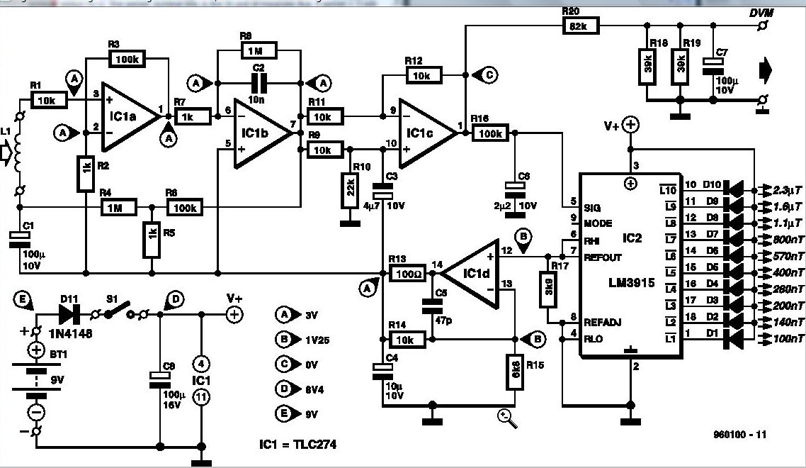
Some experts believe that static magnetic fields (SMFs) may affect the physical well-being of individuals. If one subscribes to this viewpoint, the magnetic-field meter described here will aid in locating sources of SMFs and assessing their strength. These results may...
magnetic field therapy
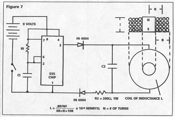
Devices capable of disabling and destroying microorganisms, including viruses, bacteria, and fungi, utilize pulsed, intense magnetic fields. These devices are not futuristic concepts but are currently available and employed in the alternative health field. Various claims exist regarding their effectiveness,...

low frequency amplifier
Gain increases by decades as the binary input decreases from 1,1 to 0,0. Minimum gain is 1 and maximum gain is 1000. More: Since the switch is static in this type of amplifier, the power dissipation of the switch will...
Automatic plant waterer
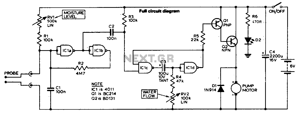
The unit consists of a sensor, timer, and electric water pump. The sensor is embedded in the soil, and when dry, the electronics operate the water pump for a preset time. The circuit is composed of a level-sensitive Schmitt trigger,...
Sleeping-Aids
The circuit generates geomagnetic fields that allow for their perception, creating an ideal environment for sound sleep. When SW2 is open (Alternate mode operation), the device operates for a pre-set duration and then pauses for the same amount of time,...
Magnetic Field Meter
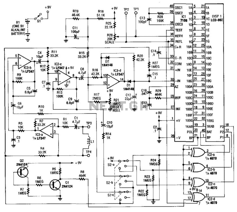
Using a pickup coil to drive an amplifier (IC3A-B-C-D), this meter circuit can be directly calibrated in field intensity units. R3/C3 and R12/C7 establish a frequency roll-off that compensates for the pickup coil's sensitivity and set a 20 kHz cut-off...
Magnetic Field Sensor circuit
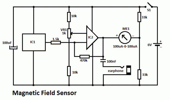
This DIY magnetic field sensor circuit is straightforward and capable of detecting both fixed magnetic fields and those that vary at audio frequencies. The device is not designed for precise measurement of magnetic field strength. A small and relatively weak...
Magnetic Field Sensor Circuit
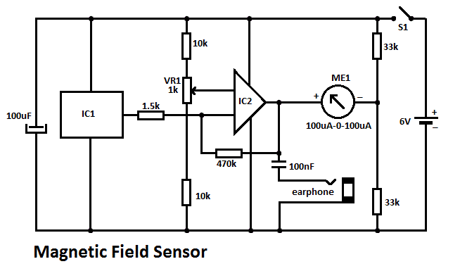
This DIY magnetic field sensor circuit is straightforward and capable of detecting both static magnetic fields and those that vary at audio frequencies. The unit is designed to be user-friendly and efficient.
The magnetic field sensor circuit typically employs a Hall...
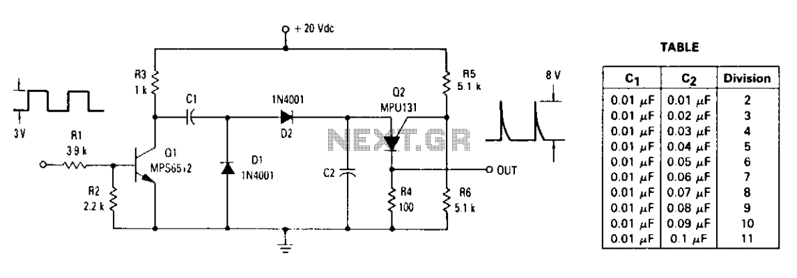
Low frequency divider
The ratio of capacitors C1 and C2 determines the division. With a positive pulse applied to the base of Q1, assume that C1 = C2 and that C1 and C2 are discharged. When Q1 turns off, both C1 and C2...