


TENS Circuits
#TENS
#muscle stimulation
#audio transformer
#medical
#DIY
#safety warning
#high voltage
#experimental
#health
#caution
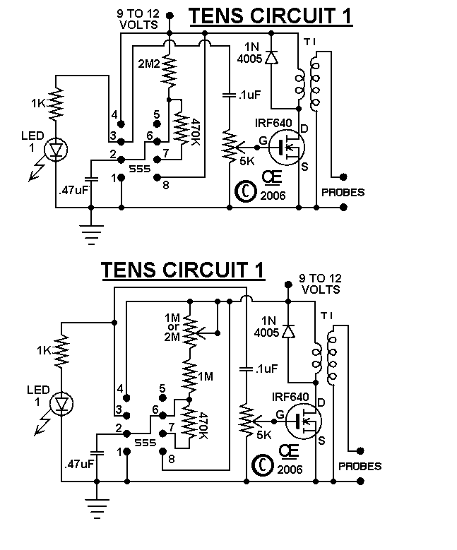
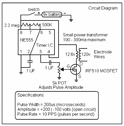
Description: The circuits were originally designed for an individual with muscle issues. Although they were reported to function effectively, the use of these devices is not recommended for anyone, and no responsibility or liability is accepted for their assembly or use. In Circuits 1 and 2, "T1" refers to a small audio transformer with an 8-ohm impedance, where the winding connected to the FET and the larger winding is connected to the probe and ground. It is advised to utilize a "Mode" Transformer, Part Number 60-282-0. The Base connects to the Gate, the Collector to the Drain, and the Emitter to the Source. This modification will lead to a lower power output, but functionality is maintained. The PCB for the Ten-1 includes provisions for a potentiometer to control the frequency of the 555 timer. If the control is not desired, it can be shorted out. For those who wish to utilize this control, a 1M or 2M potentiometer should be used, and R1 (2M2) should be changed to a 1M resistor.
The described circuit includes several critical components that contribute to its operation. The audio transformer (T1) plays a vital role in signal coupling, allowing for impedance matching between the circuit and the load. The 8-ohm impedance is suitable for driving speakers or other low-impedance loads. The Field Effect Transistor (FET) serves as a switch or amplifier, with the Base, Collector, and Emitter connections indicating that a bipolar junction transistor (BJT) configuration is being referenced, which is essential for controlling the output signal.
The recommended Mode Transformer (Part Number 60-282-0) is specifically designed to optimize performance in this application. The connection of the Base to the Gate, Collector to the Drain, and Emitter to the Source suggests that the circuit may be intended for use in a switching application where the FET is being driven by a BJT.
The inclusion of a potentiometer for frequency control of the 555 timer allows for flexibility in tuning the circuit's operational frequency. The 555 timer is widely used for generating precise timing pulses and can be configured in various modes, such as astable or monostable. The option to short the potentiometer provides a straightforward method for users who prefer a fixed frequency operation.
For those opting to implement the frequency control, selecting a potentiometer with a resistance value of 1M or 2M will affect the timing characteristics of the 555 timer. Additionally, changing the resistor R1 from 2M2 to 1M will further modify the timing cycle, allowing for a broader range of frequency adjustments. This design consideration is crucial for applications requiring precise timing and control.
Overall, the circuit design emphasizes a balance between functionality and user control, with specific recommendations for component values and configurations to ensure optimal performance.I initially designed these circuits for a friend who had muscle problems and while he says they did work well for him, I "DO NOT" RECOMMEND THE USE OF THESE DEVICES BY ANYONE FOR ANY REASON. I ACCEPT NO RESPONSIBILITY OR LIABILITY FROM THERE ASSEMBLY OR USE IN ANYWAY. "T1" in Circuits "1 & 2" is a small audio transformer with the 8 ohm impedance w inding connected to the Fet and the larger winding connected to the probe and ground. I Recommend using a "Mode" Transformer, Part Number 60-282-0. The Base connects to the Gate, the Collector to the Drain, and the Emitter to the Source. This change will result in a "Lower Power Output", but it still works. The PCB for the Ten-1 also has provisions for a pot to control the Frequency of the 555. If you don`t want to use this control, Just Short it out. If you do want this control, use a 1M or 2M Pot and Change R1 (2M2) to a 1M.
The described circuit includes several critical components that contribute to its operation. The audio transformer (T1) plays a vital role in signal coupling, allowing for impedance matching between the circuit and the load. The 8-ohm impedance is suitable for driving speakers or other low-impedance loads. The Field Effect Transistor (FET) serves as a switch or amplifier, with the Base, Collector, and Emitter connections indicating that a bipolar junction transistor (BJT) configuration is being referenced, which is essential for controlling the output signal.
The recommended Mode Transformer (Part Number 60-282-0) is specifically designed to optimize performance in this application. The connection of the Base to the Gate, Collector to the Drain, and Emitter to the Source suggests that the circuit may be intended for use in a switching application where the FET is being driven by a BJT.
The inclusion of a potentiometer for frequency control of the 555 timer allows for flexibility in tuning the circuit's operational frequency. The 555 timer is widely used for generating precise timing pulses and can be configured in various modes, such as astable or monostable. The option to short the potentiometer provides a straightforward method for users who prefer a fixed frequency operation.
For those opting to implement the frequency control, selecting a potentiometer with a resistance value of 1M or 2M will affect the timing characteristics of the 555 timer. Additionally, changing the resistor R1 from 2M2 to 1M will further modify the timing cycle, allowing for a broader range of frequency adjustments. This design consideration is crucial for applications requiring precise timing and control.
Overall, the circuit design emphasizes a balance between functionality and user control, with specific recommendations for component values and configurations to ensure optimal performance.I initially designed these circuits for a friend who had muscle problems and while he says they did work well for him, I "DO NOT" RECOMMEND THE USE OF THESE DEVICES BY ANYONE FOR ANY REASON. I ACCEPT NO RESPONSIBILITY OR LIABILITY FROM THERE ASSEMBLY OR USE IN ANYWAY. "T1" in Circuits "1 & 2" is a small audio transformer with the 8 ohm impedance w inding connected to the Fet and the larger winding connected to the probe and ground. I Recommend using a "Mode" Transformer, Part Number 60-282-0. The Base connects to the Gate, the Collector to the Drain, and the Emitter to the Source. This change will result in a "Lower Power Output", but it still works. The PCB for the Ten-1 also has provisions for a pot to control the Frequency of the 555. If you don`t want to use this control, Just Short it out. If you do want this control, use a 1M or 2M Pot and Change R1 (2M2) to a 1M.
Various Schematics and Diagrams
Energy storage capacitors in even the smallest disposable camera flash powered by a 1.5 V AA battery can be hazardous under certain conditions. Line-powered devices, regardless of size, may present additional risks due to high power at high voltage and...
High voltage switching stabilized voltage supply circuit
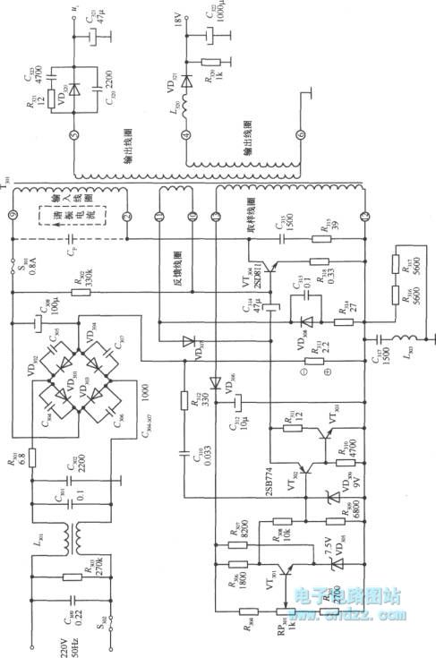
A high voltage switching stabilized voltage supply circuit is illustrated in the diagram. This is the switching power supply for an 80P type color television. It utilizes auto-excitation and a PWM circuit. The output is isolated from the power system,...
High Voltage Stun Guns
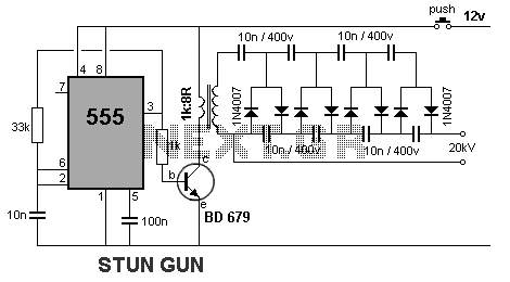
This device generates high-voltage pulses that disrupt muscles and the nervous system, causing mental confusion in anyone who comes into contact with it. It can be utilized against aggressive animals or attackers; however, it is important to note that this...
Using a TENS for relief from RLS or Restless Legs Syndrome
A TENS (Transcutaneous Electrical Nerve Stimulation) device utilizes a battery power source to generate a high-voltage, low-current signal at a specified frequency and duration. This electrical current is applied externally to the skin using adhesive foam electrode pads. More advanced...

turret diy
For maximum mini-security, this RC Tupperware Turret delivers a formidable deterrent against food theft. While it lacks motion sensors, potential food thieves will think twice before attempting to swipe baked goods. This 11-hour project, designed by Chris of PyroElectro, emphasizes...

Low Voltage to 30 kV Out
The circuit detailed in this document is designed to produce up to 30 kilovolts or more from a low-voltage DC source using a flyback transformer (LOPT) salvaged from a black-and-white or color television or computer monitor. With a typical 12...
Solid State Tesla Coil/High Voltage Generator
This circuit is designed to demonstrate high-frequency high voltage, capable of producing approximately 30 kV, depending on the transformer utilized. It is cost-effective and simple to construct, primarily using a standard TV flyback transformer. The circuit can power lasers, demonstrate...
The 25-30kV DC Generator
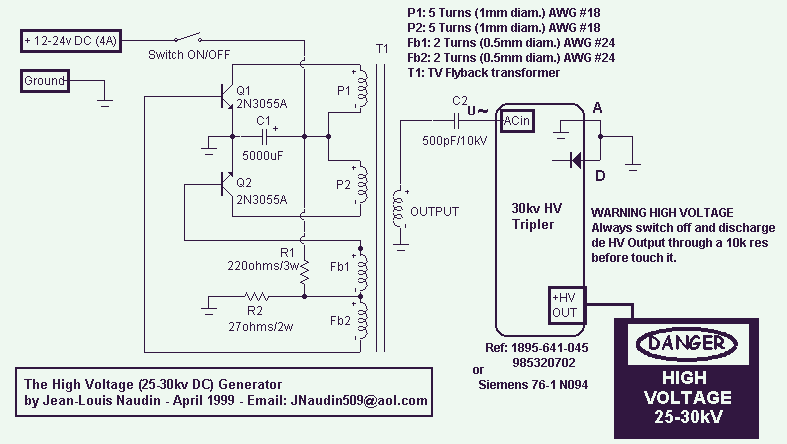
This High Voltage power supply is able to generate up to 25-30kV DC Output from a 12-24v DC input. With a fully adjustable DC input power supply (0-24V/4A), it is possible to adjust the HV output between 5 to 30kV....
Ultra high voltage generator
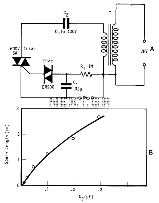
By repetitively charging and discharging a capacitor through the primary winding of an induction coil with high voltage, an ultra-high electromotive force (emf) is induced in the secondary winding. Switching is performed by a triac, which is triggered by a...