


A block diagram of AN6657 and basic application circuit
#AN6657
#H-bridge
#speed control
#driver chip
#dual in-line package
#dual flat package
#motor driver
#16-pin
#internal circuit
#output
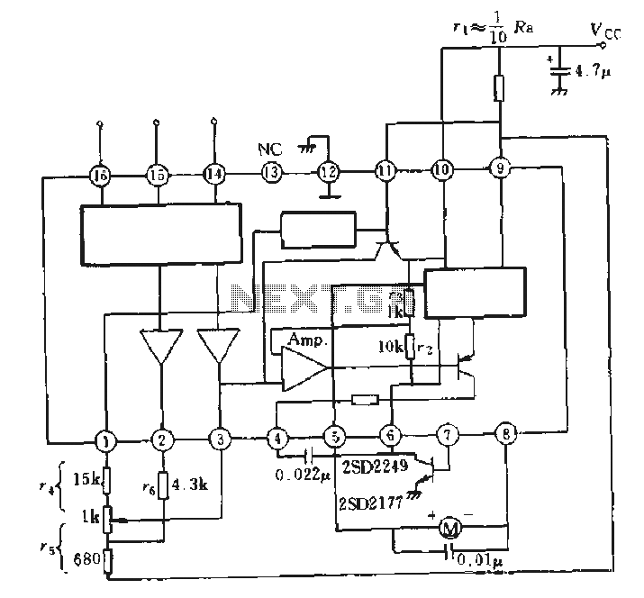
Description: The AN6657 is a 16-pin dual in-line plastic package, while the AN6657S features a 16-pin dual flat plastic package. The speed control function operates with an internal H-bridge driver chip circuit, utilizing pins 5 and 8 for H-bridge driver outputs to control the motor. When pin 5 is positive, the motor operates in one direction; when pin 8 is positive, the motor reverses direction. The positive supply for the H-bridge is connected to pins 9 and 11, which is linked to an external electrical contact resistance (R VCC). The H-bridge arm is connected to pin 6, and an external NPN transistor is used to ground the circuit.
The AN6657 and AN6657S integrated circuits are designed for motor control applications, specifically for driving DC motors with bidirectional capability. The internal H-bridge configuration allows for efficient control of motor direction and speed by utilizing pulse width modulation (PWM) techniques. The device is capable of handling the required current levels to operate small to medium-sized motors, making it suitable for various applications, including robotics, automation systems, and consumer electronics.
In operation, the H-bridge driver outputs on pins 5 and 8 are responsible for controlling the polarity of the voltage applied to the motor terminals. When pin 5 is activated (set to a high logic level), current flows through the motor in one direction, causing it to rotate forward. Conversely, activating pin 8 reverses the polarity, allowing the motor to rotate in the opposite direction. The ability to control motor speed is achieved by modulating the duty cycle of the PWM signal applied to the enable pin, which is typically connected to an external control circuit.
The positive supply voltage for the H-bridge is provided through pins 9 and 11. This supply voltage must be stable and within the specified operating range to ensure reliable motor operation. Additionally, the external electrical contact resistance (R VCC) plays a crucial role in limiting the current and protecting the integrated circuit from overcurrent conditions.
Pin 6 serves as the connection point for the H-bridge arm, while the external NPN transistor connected to this pin is utilized to ground the circuit, enabling or disabling the motor operation based on the control signals. This configuration allows for enhanced control over the motor's behavior, including features such as braking and coasting.
Overall, the AN6657 series provides a compact and efficient solution for motor control applications, integrating essential features into a single package to simplify design and implementation.AN6657 is a 16-pin dual in-line plastic package, AN6657S 16-pin dual flat plastic package. 1. Speed Control works with internal H-bridge driver chip circuit, 5 and 8 feet H-bridge driver output, then charged motor. When 5 feet is positive, the motor is transferred; when 8 feet is positive, reverse the motor. H-bridge positive supply 9 and 11 feet, after an external electrical contact resistance r vcc. H bridge arm connected to 6 feet, after an external NPN transistor is grounded, see solid
The AN6657 and AN6657S integrated circuits are designed for motor control applications, specifically for driving DC motors with bidirectional capability. The internal H-bridge configuration allows for efficient control of motor direction and speed by utilizing pulse width modulation (PWM) techniques. The device is capable of handling the required current levels to operate small to medium-sized motors, making it suitable for various applications, including robotics, automation systems, and consumer electronics.
In operation, the H-bridge driver outputs on pins 5 and 8 are responsible for controlling the polarity of the voltage applied to the motor terminals. When pin 5 is activated (set to a high logic level), current flows through the motor in one direction, causing it to rotate forward. Conversely, activating pin 8 reverses the polarity, allowing the motor to rotate in the opposite direction. The ability to control motor speed is achieved by modulating the duty cycle of the PWM signal applied to the enable pin, which is typically connected to an external control circuit.
The positive supply voltage for the H-bridge is provided through pins 9 and 11. This supply voltage must be stable and within the specified operating range to ensure reliable motor operation. Additionally, the external electrical contact resistance (R VCC) plays a crucial role in limiting the current and protecting the integrated circuit from overcurrent conditions.
Pin 6 serves as the connection point for the H-bridge arm, while the external NPN transistor connected to this pin is utilized to ground the circuit, enabling or disabling the motor operation based on the control signals. This configuration allows for enhanced control over the motor's behavior, including features such as braking and coasting.
Overall, the AN6657 series provides a compact and efficient solution for motor control applications, integrating essential features into a single package to simplify design and implementation.AN6657 is a 16-pin dual in-line plastic package, AN6657S 16-pin dual flat plastic package. 1. Speed Control works with internal H-bridge driver chip circuit, 5 and 8 feet H-bridge driver output, then charged motor. When 5 feet is positive, the motor is transferred; when 8 feet is positive, reverse the motor. H-bridge positive supply 9 and 11 feet, after an external electrical contact resistance r vcc. H bridge arm connected to 6 feet, after an external NPN transistor is grounded, see solid
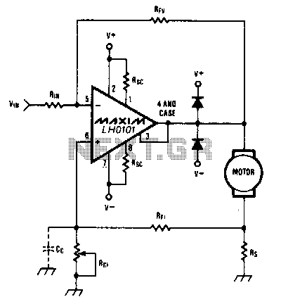
Constant-speed-motor-driver
When the torque load on the motor increases, its current also rises. This increase in current is detected across Rs, and positive feedback is applied to the noninverting terminal of the LH0101, which in turn raises the motor voltage to...
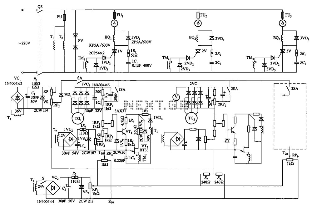
Multi-unit slip motor speed control system synchronous operation circuit
Collaboration with the dancers balanced bridge long on the porcelain unit. A sync adjustment rheostat speed control system is shown in Figure 3. The principle of speed control for electro-magnetic and photoelectric dancers is similar. The main motor (BQ2) allows...
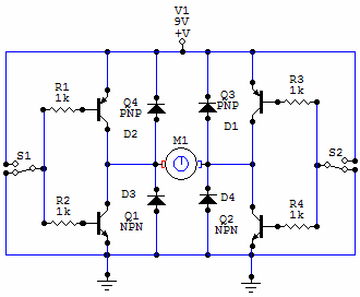
Another simple H-Bridge circuit
You have 4 transistors, wired as ON OFF switches. Two signal lines allow you to run the motor in one direction, when reversed, the motor runs in the other direction. It's very straightforward to use and build, but be careful...
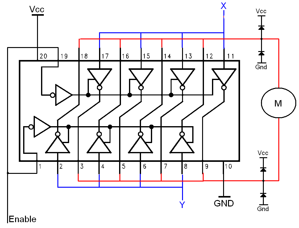
Simple H-bridges Tutorial
The H-bridge is a well-known and widely used circuit configuration for driving brushed DC motors. It enables straightforward control of motor direction, allowing for both forward and reverse operation.
The H-bridge circuit consists of four switches, typically implemented using transistors or...
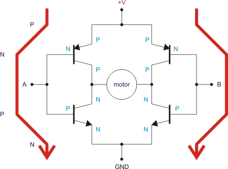
H Bridge Qik 2s12v10 Dual Serial
This H-bridge is currently being used for a Sumo-bot and is considered suitable for medium-sized motors, handling up to 30A peak and 13A in continuous mode. The cost is approximately $75 plus shipping. An H-bridge serves as an intermediary control...
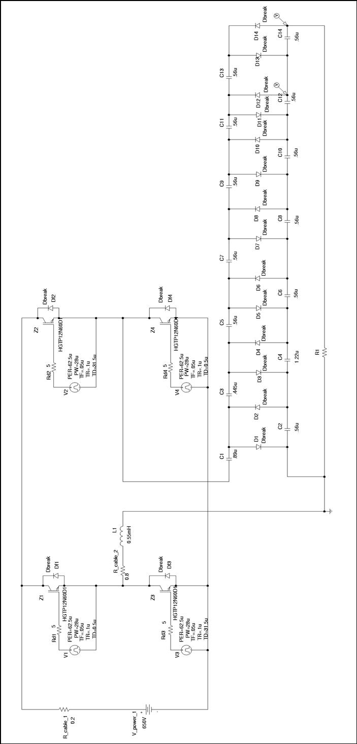
h bridge voltage multiplier at low voltage
Thesis by Rafael Bräg at the University of Canterbury, New Zealand, in cooperation with the Universität Karlsruhe, Institut Elektrotechnik und Hochspannungstechnik.
The thesis presents a comprehensive study conducted by Rafael Bräg, focusing on advancements in the field of electrical engineering. The...
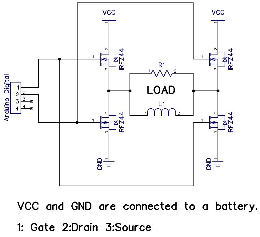
H-Bridge on a Breadboard
The H-Bridge is a circuit that can drive a motor in both forward and reverse directions. It can be a straightforward circuit that requires only a few components.
The H-Bridge circuit is a fundamental configuration used in motor control applications, allowing...
STHS Computer Technology
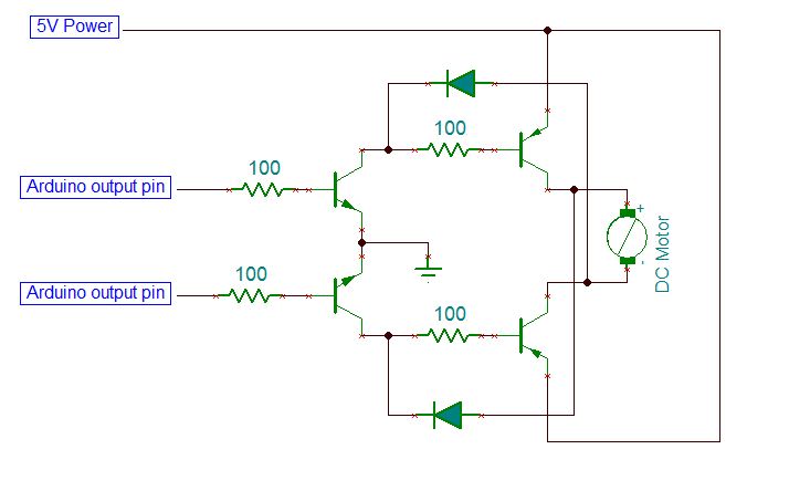
On the breadboard, construct two bi-directional motor control circuits, commonly referred to as "H-bridge" circuits. These circuits will manage the two DC motors that propel the wheels. Each circuit will have two wires connected to the Arduino (one for forward...
Custom Motor Driver
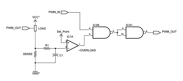
This chapter was removed from Applied Robotics 2 due to space constraints. It addresses general motor control issues and details the construction of a 5-amp motor driver. The principles discussed can be applied to larger motor controllers. Although commercially available...