


CPD type forklift battery control circuit
#forklift
#DC motor
#battery control
#electric drive
#series motor
#mechanical transmission
#pump motor
#power management
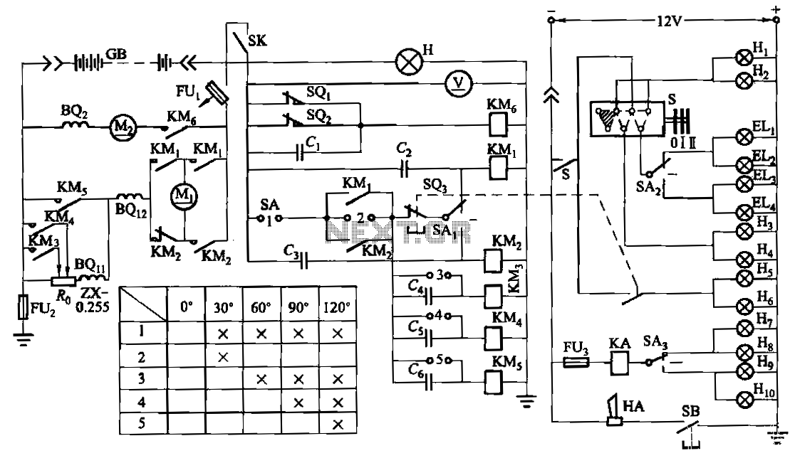
Description: The forklift electric drive system comprises two DC series motors and associated control equipment. A 4.5 kW electric motor drives the vehicle through a mechanical transmission mechanism, enabling forward and backward movement of the forklift. A 6 kW pump motor operates a hydraulic mechanism that controls mast tilting, lifting, and forward movement of appendages. The system includes limit switches SQ1 and SQ2 for the pump. In the event of an emergency brake activation, the limit switch opens, causing the normally closed contacts to disconnect, which releases contactors KM1 or KM2 and leads to the stalling of motor M1.
The forklift electric drive system is designed to provide reliable and efficient operation for material handling tasks. The two DC series motors are utilized for their high starting torque, making them suitable for the heavy loads typically handled by forklifts. The 4.5 kW drive motor (M1) is responsible for propelling the forklift, with its output connected to a mechanical transmission that translates the motor's rotational force into linear motion. This configuration allows for smooth acceleration and deceleration during operation, enhancing the operator's control over the vehicle.
The 6 kW pump motor (M2) is specifically dedicated to powering the hydraulic system, which is essential for the operation of the forklift's mast and appendages. The hydraulic mechanism allows for precise control of mast movements, such as tilting and lifting, which are critical for loading and unloading materials. The pump's output is regulated by limit switches SQ1 and SQ2, which ensure that the hydraulic system operates within safe parameters, preventing overextension or damage to the hydraulic components.
In terms of safety, the system incorporates an emergency brake feature that is activated through a limit switch. When the emergency brake is engaged, the limit switch opens the normally closed contacts, effectively cutting power to the drive motor and releasing the contactors. This safety mechanism is crucial for preventing unintended movement of the forklift, particularly in emergency situations.
Overall, this electric drive system for the forklift is engineered to deliver robust performance while prioritizing safety and operational efficiency. The integration of DC series motors with hydraulic control mechanisms exemplifies a well-thought-out design tailored for the demands of material handling environments.Forklift electric drive system consists of two DC series motors and control equipment. 4. 5kW electric motor driving through a mechanical transmission mechanism Mi, driving forklifts for forward and backward travel. 6.skW pump motor M2 machine after machine driven by a hydraulic mechanism mast tilting, lifting or forward movement and appendages. Figure, SQi, SQ2 to pump limit switches. When the emergency brake, limit switch so. The normally closed contacts disconnect, contactors KMi or KMz release, motor Mi stall.
The forklift electric drive system is designed to provide reliable and efficient operation for material handling tasks. The two DC series motors are utilized for their high starting torque, making them suitable for the heavy loads typically handled by forklifts. The 4.5 kW drive motor (M1) is responsible for propelling the forklift, with its output connected to a mechanical transmission that translates the motor's rotational force into linear motion. This configuration allows for smooth acceleration and deceleration during operation, enhancing the operator's control over the vehicle.
The 6 kW pump motor (M2) is specifically dedicated to powering the hydraulic system, which is essential for the operation of the forklift's mast and appendages. The hydraulic mechanism allows for precise control of mast movements, such as tilting and lifting, which are critical for loading and unloading materials. The pump's output is regulated by limit switches SQ1 and SQ2, which ensure that the hydraulic system operates within safe parameters, preventing overextension or damage to the hydraulic components.
In terms of safety, the system incorporates an emergency brake feature that is activated through a limit switch. When the emergency brake is engaged, the limit switch opens the normally closed contacts, effectively cutting power to the drive motor and releasing the contactors. This safety mechanism is crucial for preventing unintended movement of the forklift, particularly in emergency situations.
Overall, this electric drive system for the forklift is engineered to deliver robust performance while prioritizing safety and operational efficiency. The integration of DC series motors with hydraulic control mechanisms exemplifies a well-thought-out design tailored for the demands of material handling environments.Forklift electric drive system consists of two DC series motors and control equipment. 4. 5kW electric motor driving through a mechanical transmission mechanism Mi, driving forklifts for forward and backward travel. 6.skW pump motor M2 machine after machine driven by a hydraulic mechanism mast tilting, lifting or forward movement and appendages. Figure, SQi, SQ2 to pump limit switches. When the emergency brake, limit switch so. The normally closed contacts disconnect, contactors KMi or KMz release, motor Mi stall.
DC Motor Reversing Circuit
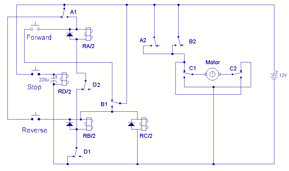
A DC motor reversing circuit using non-latching push button switches. Relays control forward, stop, and reverse action, and the motor cannot be switched from forward to reverse unless the stop switch is pressed first.
The described circuit employs a system of...
DC Motor Speed Controller
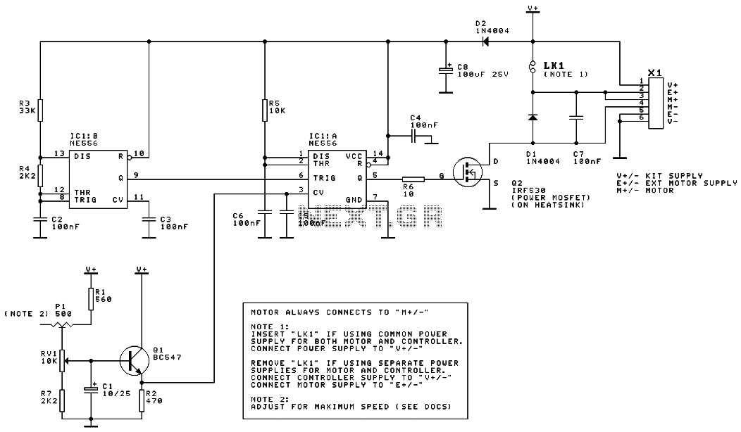
This is the schematic diagram of a DC motor speed controller circuit. The circuit utilizes two oscillators/timers that are configured as a Pulse Width Modulator (PWM). The timer chip used in this circuit is a dual NMOS timer/oscillator.
The DC motor...
DC Motor Control Circuit
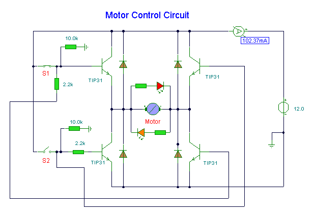
S1 and S2 are normally open, push-to-close, momentary switches. The diodes may be red or green and serve solely as indicators of direction. The TIP31 transistors may need to be adjusted based on the motor specifications. It is important to...
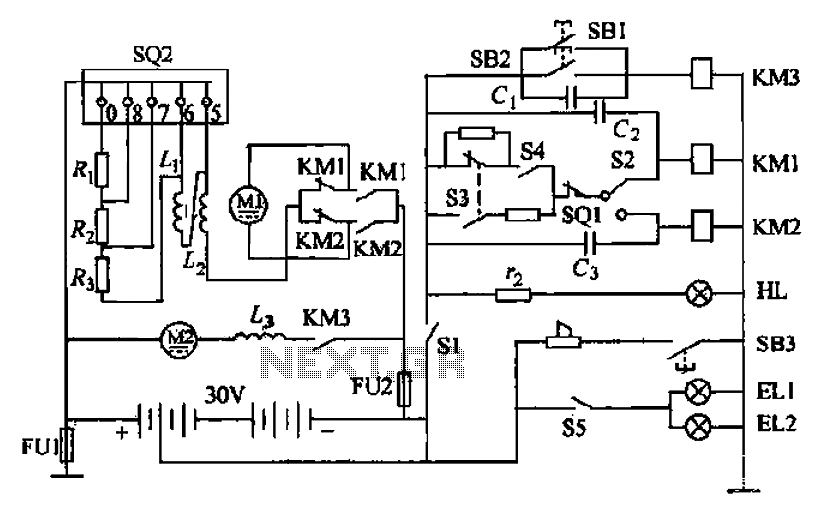
Forklift battery circuit
Battery forklifts are commonly used as stacking and handling tools in railway stations, docks, and warehouses. The battery shape and electrical control circuitry are depicted in the schematic. The system consists of batteries connected in series to form a 30V...
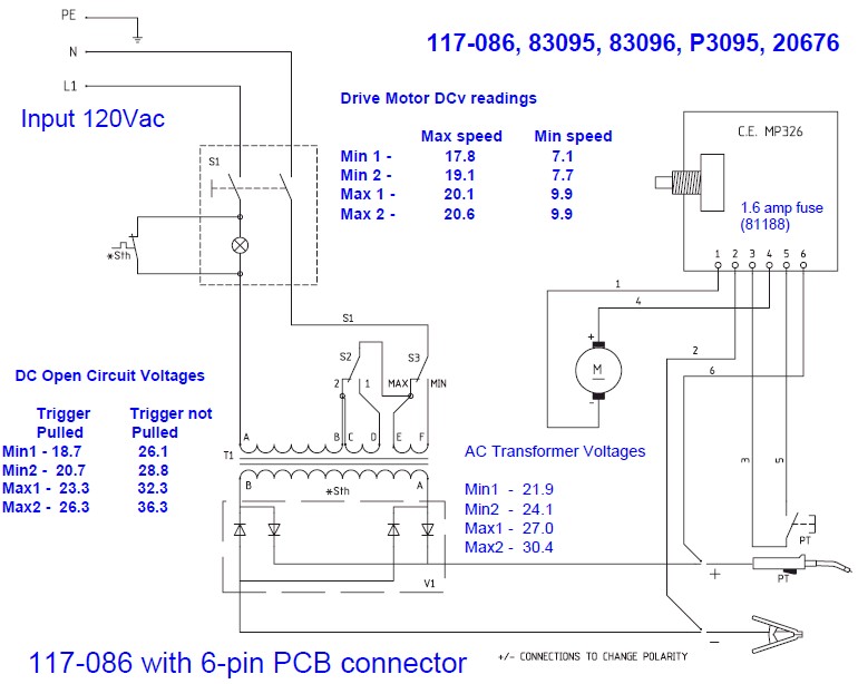
Need Help Deciphering Circuit Board Schematic
The wire speed DC motor consistently receives approximately 20 volts, irrespective of the switch position on the nozzle handle. The switch has been tested with an ohmmeter and functions properly. Even after disconnecting the switch from the circuit board, the...
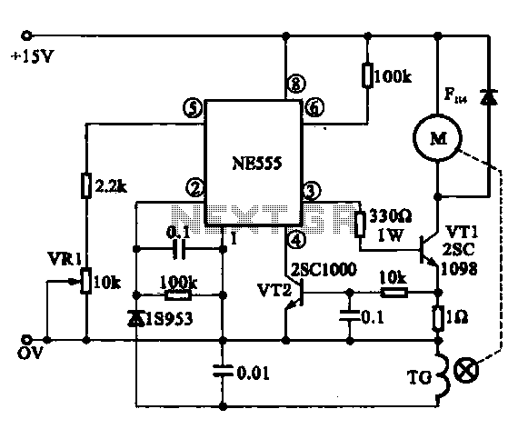
Miniature DC Motor Speed Control circuit
The Miniature DC Motor Speed Control circuit is designed to maintain a steady speed for micro motors, as illustrated in Figure 8-32. The circuit utilizes a voltage feedback mechanism suitable for applications such as tape recording machines that employ miniature...
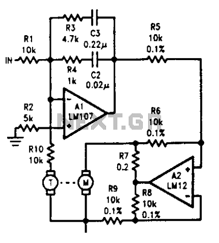
Motor-tachometer speed control
The tachometer, mounted on the same shaft as the DC motor, functions as a generator, producing a DC output voltage that is proportional to the motor's speed. A summing amplifier, labeled as Al, manages its output to ensure that the...
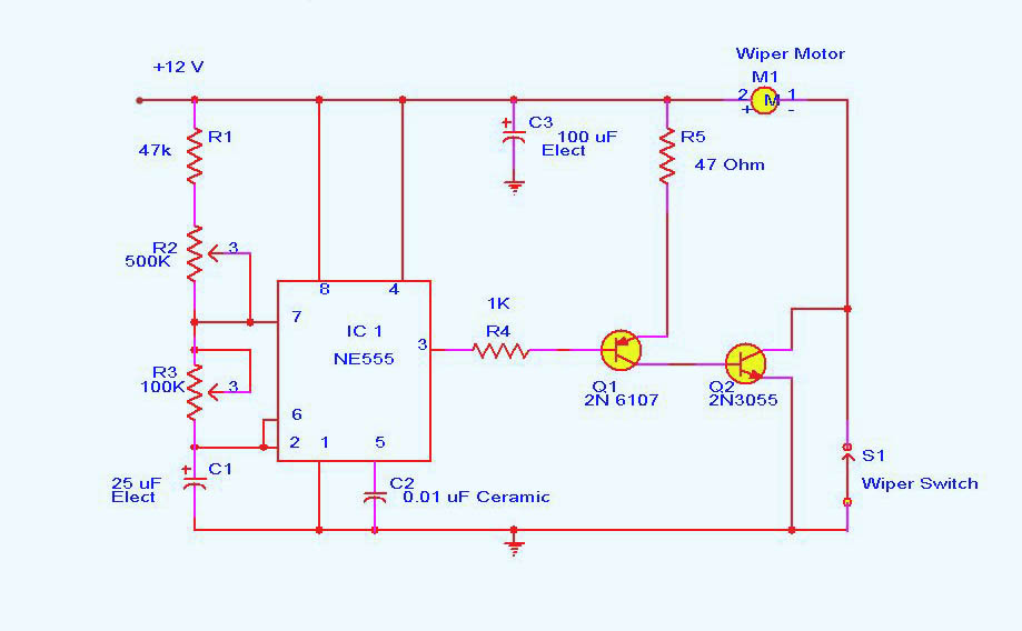
motor controller
DC motor control circuit using NE555. The 555 timer circuit has numerous applications. For those unfamiliar with its functionalities, an authoritative book can provide valuable insights. CircuitsToday offers an online store featuring reviews of three highly recommended books that delve...
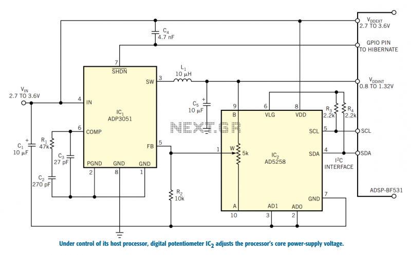
Control a processor`s power supply in real time
In battery-powered applications in which power management is key, a microprocessor may adjust its core voltage corresponding to an increase or a decrease in clock speed, allowing full processing power when necessary but not wasting excess power when idle. The...