


Forklift battery circuit
#forklift
#battery
#charging circuit
#warehouse equipment
#industrial
#power management
#energy storage
#heavy machinery
#electric vehicles
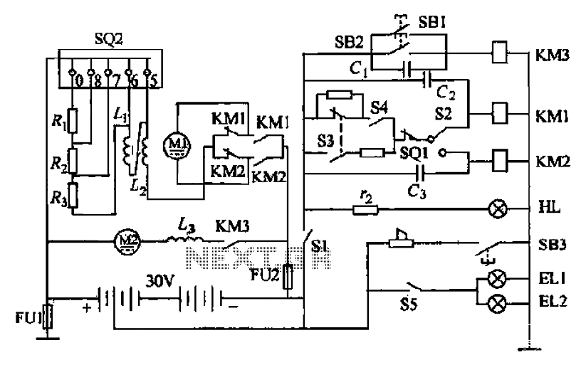
Description: Battery forklifts are commonly used as stacking and handling tools in railway stations, docks, and warehouses. The battery shape and electrical control circuitry are depicted in the schematic. The system consists of batteries connected in series to form a 30V DC power supply. Motor M1 drives the forklift, which operates at two speeds through a gear wheel drive mechanism, allowing movement forward or backward with the shovel. Motor M2 is responsible for powering the high-pressure oil pump that feeds the hydraulic system for forklift operation. The system includes an electric lock switch (S1), a direction switch (S2), a foot switch (SO1), and a speed controller pedal (S02). The electric lock switch S1 must be closed to indicate that power is available. The direction switch S2 is adjusted to set the desired movement direction of the forklift. After releasing the parking brake handle and the foot brake, the foot switch SO1 is closed, allowing the speed controller pedal S02 to engage and activate the main switch S3.
The battery forklift operates on a well-defined electrical and mechanical structure that ensures efficient handling and maneuverability. The series connection of batteries provides a stable 30V DC output, which is essential for powering the motors and hydraulic systems. Motor M1, a two-speed series motor, is designed to deliver torque and speed control through a gear mechanism, facilitating the lifting and lowering of loads. The gear wheel drive system enables the forklift to navigate through tight spaces and perform precise movements.
Motor M2 plays a critical role in the hydraulic system, powering a high-pressure oil pump that enables the lifting mechanism of the forklift. This motor must operate reliably under varying load conditions to maintain the efficiency of the hydraulic system. The integration of the electric lock switch (S1) ensures that the forklift cannot be operated unless it is safe to do so, preventing accidental activation.
The direction switch (S2) allows the operator to select forward or backward movement, enhancing operational flexibility. The foot switch (SO1) serves as a safety feature, ensuring that the forklift can only be activated when the operator is ready and in control. The speed controller pedal (S02) provides a means to modulate the speed of the forklift, allowing for smooth acceleration and deceleration.
In summary, the design of the battery forklift incorporates essential components such as motors, switches, and control circuitry to create a robust and user-friendly handling tool for various industrial applications. Proper understanding and management of these components are vital for maintaining operational efficiency and safety in the workplace. Battery forklifts are railway stations, docks, warehouses balloon-like plant in two commonly used as a stacking and handling tools. Pictured It forklift battery shape and elect rical control circuitry, circle 2-18b It is composed of batteries in series battery electric forklift electric control path. GB is a concatenation of the 30V DC battery power supply. Motor Ml is driving the motor, series motor is a two-speed, through a gear wheel drive mechanism, drive things forward or backward with the shovel.
Granville string electric motor M2 is the motor for drag high international oil pump, high pressure oil input to the hydraulic system to operate the fork lift. Sl electric lock switch, S2 is a direction switch, soi for the foot switch. s02 speed controller pedal. The forklift and the governor will start the electric lock switch sl closed HL power indicator light, said power had access circuit, make ready supply.
The direction of the switch S2 handle into the desired direction, namely forklift forward or backward position. Release the parking brake handle stern, release the foot brake and the car, so that the foot switch is closed soi reset, and then gently depress the pedal speed controller SQ2 to dynamic contact with the stationary contact 0 contact, so that the entire mace switch S3 closed sets.
The battery forklift operates on a well-defined electrical and mechanical structure that ensures efficient handling and maneuverability. The series connection of batteries provides a stable 30V DC output, which is essential for powering the motors and hydraulic systems. Motor M1, a two-speed series motor, is designed to deliver torque and speed control through a gear mechanism, facilitating the lifting and lowering of loads. The gear wheel drive system enables the forklift to navigate through tight spaces and perform precise movements.
Motor M2 plays a critical role in the hydraulic system, powering a high-pressure oil pump that enables the lifting mechanism of the forklift. This motor must operate reliably under varying load conditions to maintain the efficiency of the hydraulic system. The integration of the electric lock switch (S1) ensures that the forklift cannot be operated unless it is safe to do so, preventing accidental activation.
The direction switch (S2) allows the operator to select forward or backward movement, enhancing operational flexibility. The foot switch (SO1) serves as a safety feature, ensuring that the forklift can only be activated when the operator is ready and in control. The speed controller pedal (S02) provides a means to modulate the speed of the forklift, allowing for smooth acceleration and deceleration.
In summary, the design of the battery forklift incorporates essential components such as motors, switches, and control circuitry to create a robust and user-friendly handling tool for various industrial applications. Proper understanding and management of these components are vital for maintaining operational efficiency and safety in the workplace. Battery forklifts are railway stations, docks, warehouses balloon-like plant in two commonly used as a stacking and handling tools. Pictured It forklift battery shape and elect rical control circuitry, circle 2-18b It is composed of batteries in series battery electric forklift electric control path. GB is a concatenation of the 30V DC battery power supply. Motor Ml is driving the motor, series motor is a two-speed, through a gear wheel drive mechanism, drive things forward or backward with the shovel.
Granville string electric motor M2 is the motor for drag high international oil pump, high pressure oil input to the hydraulic system to operate the fork lift. Sl electric lock switch, S2 is a direction switch, soi for the foot switch. s02 speed controller pedal. The forklift and the governor will start the electric lock switch sl closed HL power indicator light, said power had access circuit, make ready supply.
The direction of the switch S2 handle into the desired direction, namely forklift forward or backward position. Release the parking brake handle stern, release the foot brake and the car, so that the foot switch is closed soi reset, and then gently depress the pedal speed controller SQ2 to dynamic contact with the stationary contact 0 contact, so that the entire mace switch S3 closed sets.
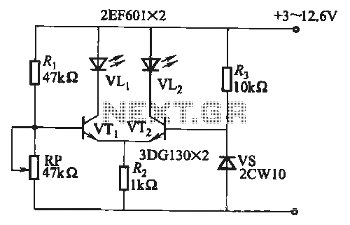
Battery discharge status indicator circuit
When the battery voltage is within the range of 7 to 12.6V, the light-emitting diode VLi illuminates, maintaining a consistent brightness. If the battery voltage drops below 7V, VLi begins to emit a red light, and the brightness of the...
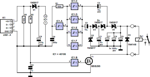
Computer Off Switch
How often does it happen that a user shuts down Windows and then forgets to turn off the computer? This circuit automates that process. After Windows is shut down, a click occurs a second later, disconnecting the PC from the...
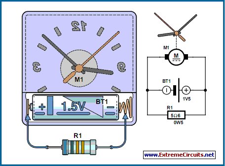
Hyper-Simple Battery Capacity Tester
The circuit described is suitable for indicating the capacity of a battery using a low-cost electric clock. By connecting a resistor across the battery terminals, the battery discharges at a faster rate than it would with the clock alone. Selecting...
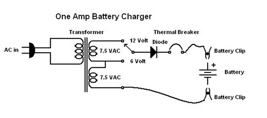
One Amp Battery Charger
When this battery charger was purchased in 1970, it was not anticipated that it would still be relevant today. At that time, the owner had an old car with a weak battery that struggled to start in cold weather, prompting...
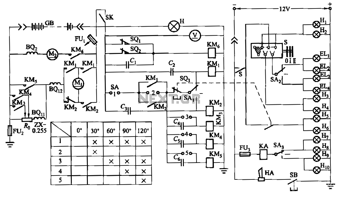
CPD type forklift battery control circuit
The forklift electric drive system comprises two DC series motors and associated control equipment. A 4.5 kW electric motor drives the vehicle through a mechanical transmission mechanism, enabling forward and backward movement of the forklift. A 6 kW pump motor...
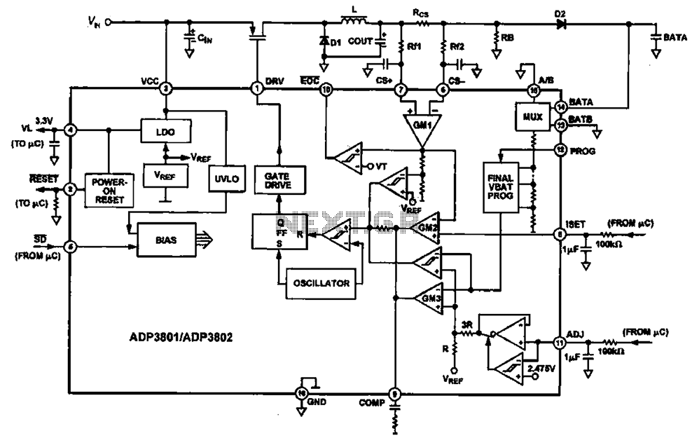
Charging circuit diagram personal work
Charging circuit diagram for personal work based on the operating principle of ADP3801/3802 charging circuit.
The ADP3801/3802 is a highly integrated battery charger controller designed for Li-ion and Li-polymer batteries. The charging circuit typically consists of several key components including the...
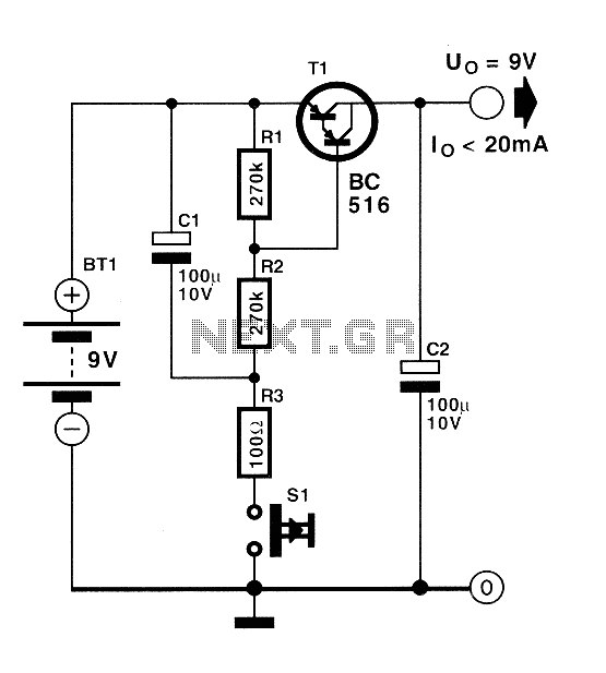
Automatic switch for batteries
Currently, batteries are becoming increasingly powerful, serving as the sole energy source for portable electronic devices. The rapid evolution of battery technology has prompted manufacturers of electronic equipment to strive for reduced power consumption in their products, enabling them to...
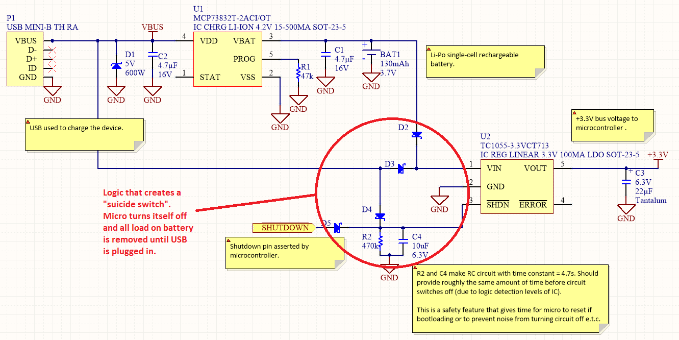
Power Management
Overview Disabling Sections of a Circuit The "Suicide Switch" Overview Power management is a significant design consideration for battery-powered devices.
Power management is a crucial aspect of circuit design, particularly in battery-powered applications where energy efficiency directly impacts the operational lifespan...
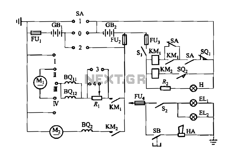
It ZD1 type forklift battery control circuit
Denote cam controller SA 1 contact closure case. M1 is 1.35 kW driving motor, M2 is a 4 kW pump motor.
The circuit involves a cam controller designated as SA 1, which is responsible for managing the operation of two...