


DC Motor-Driver H-Bridge Circuit
#DC motor
#H-bridge
#motor driver
#forward/reverse
#speed control
#power source
#gearhead motor
#PWM
#bidirectional
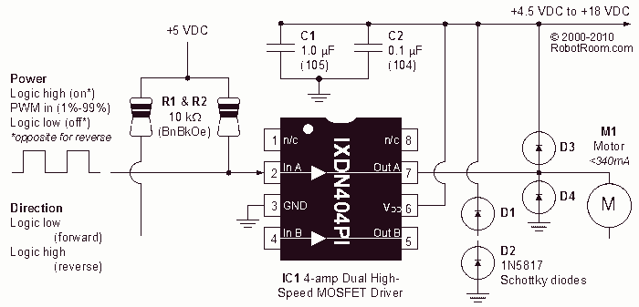
Description: A very popular circuit for driving DC motors (ordinary or gearhead) is called an H-bridge. It's called that because it looks like the capital letter 'H' on classic schematics. The great ability of an H-bridge circuit is that the motor can be driven forward or backward at any speed, optionally using a completely independent power source.
The H-bridge circuit is a crucial component in motor control applications, allowing for bidirectional control of DC motors. It consists of four switches, typically implemented using transistors or MOSFETs, arranged in an 'H' configuration. The two vertical legs of the 'H' are connected to the power supply and the motor, while the horizontal legs are the switches that control the flow of current through the motor.
To drive the motor in one direction, two switches are closed (turned on) while the other two switches are open (turned off). This allows current to flow through the motor in one direction. Reversing the motor's direction is achieved by turning off the first pair of switches and turning on the other pair, which reverses the current flow through the motor.
The speed of the motor can be controlled through Pulse Width Modulation (PWM) techniques. By rapidly switching the power to the motor on and off, the average voltage and current supplied to the motor can be adjusted, thus controlling its speed. The H-bridge can also be designed to handle various power ratings depending on the application, making it versatile for use in robotics, automotive systems, and other applications requiring motor control.
In addition to the basic H-bridge configuration, various protection features can be integrated into the design, such as flyback diodes to prevent back EMF from damaging the switches, current sensing to monitor motor load, and thermal protection to prevent overheating. These enhancements ensure reliable operation and longevity of the circuit in demanding environments.
Overall, the H-bridge circuit is an essential building block for effective DC motor control, providing flexibility in operation and ease of integration into larger systems.A very popular circuit for driving DC motors (ordinary or gearhead) is called an H-bridge. It`s called that because it looks like the capital letter `H` on classic schematics. The great ability of an H-bridge circuit is that the motor can be driven forward or backward at any speed, optionally using a completely independent power source.
The H-bridge circuit is a crucial component in motor control applications, allowing for bidirectional control of DC motors. It consists of four switches, typically implemented using transistors or MOSFETs, arranged in an 'H' configuration. The two vertical legs of the 'H' are connected to the power supply and the motor, while the horizontal legs are the switches that control the flow of current through the motor.
To drive the motor in one direction, two switches are closed (turned on) while the other two switches are open (turned off). This allows current to flow through the motor in one direction. Reversing the motor's direction is achieved by turning off the first pair of switches and turning on the other pair, which reverses the current flow through the motor.
The speed of the motor can be controlled through Pulse Width Modulation (PWM) techniques. By rapidly switching the power to the motor on and off, the average voltage and current supplied to the motor can be adjusted, thus controlling its speed. The H-bridge can also be designed to handle various power ratings depending on the application, making it versatile for use in robotics, automotive systems, and other applications requiring motor control.
In addition to the basic H-bridge configuration, various protection features can be integrated into the design, such as flyback diodes to prevent back EMF from damaging the switches, current sensing to monitor motor load, and thermal protection to prevent overheating. These enhancements ensure reliable operation and longevity of the circuit in demanding environments.
Overall, the H-bridge circuit is an essential building block for effective DC motor control, providing flexibility in operation and ease of integration into larger systems.A very popular circuit for driving DC motors (ordinary or gearhead) is called an H-bridge. It`s called that because it looks like the capital letter `H` on classic schematics. The great ability of an H-bridge circuit is that the motor can be driven forward or backward at any speed, optionally using a completely independent power source.
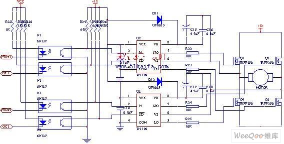
Using IRFP250 power tube H-bridge motor drive circuit
The drive circuit for the electromotor comprises a FET bridge circuit, a FET base drive circuit, a current sensor for the motor drive circuit, and a relay. The FET bridge circuit primarily consists of four high-power MOSFETs, which must possess...
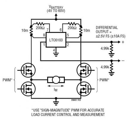
Bidirectional H-Bridge Monitoring with ADC-Friendly Differential Output
The dual outputs of the LTC6103 can be utilized independently for overload detection or combined as a differential pair to provide a bidirectional signal to an analog-to-digital converter (ADC). A typical circuit for a generic H-bridge application is illustrated. The...
PWM Speed Control Circuit Using Forward-Reverse and Regenerative Braking
This is a circuit design for a PWM speed control circuit for DC motor rotation. The circuit features two functions: Forward-Reverse operation and Regenerative Braking. The control is achieved using a MOSFET. The circuit allows for the control of a...
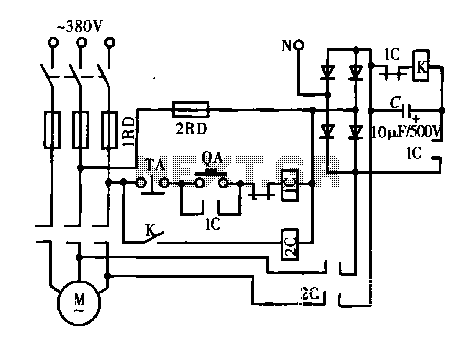
DC motor dynamic braking circuit
A DC motor is depicted in a dynamic braking circuit. When the stop button (SB2) is pressed, the contactor (KM1) is deactivated, causing its movable contact to disconnect, which interrupts the electrical voltage. Additionally, relay (KV) is activated, closing its...
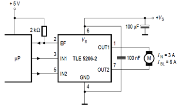
TLE5206-2 H-Bridge Circuit Application and Datasheet
The schematic below illustrates the TLE5206-2 5A H-Bridge circuit for DC motor applications. This device features an integrated power H-bridge with DMOS output stages designed specifically for driving DC motors, as indicated in the datasheet. The TLE5206-2 circuit application encompasses...

Pulse Width Modulation DC Motor Controls
This simple pulse width modulation (PWM) DC motor control addresses common issues by regulating motor speed through the application of short pulses. The duration of these pulses is varied to adjust the motor speed; longer pulses result in faster motor...
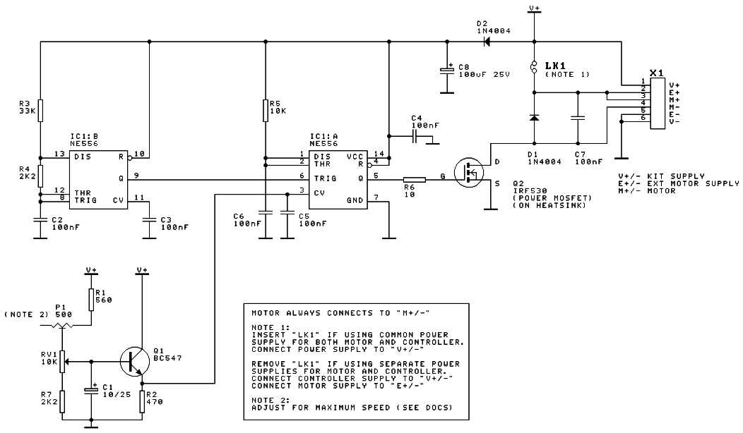
DC Motor Speed Controller
A DC motor speed controller circuit utilizes two timers configured as a Pulse Width Modulator (PWM). The integrated circuit employed for this purpose is the NE556, which is a dual timer/oscillator using NMOS technology.
The DC motor speed controller circuit operates...
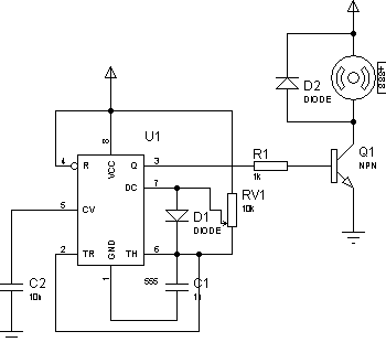
Control motor PWM schematic
There are two primary methods to control the speed of a DC motor: by varying the supply voltage and through pulse width modulation (PWM). The first method is less convenient, particularly in digital systems, as it necessitates the use of...
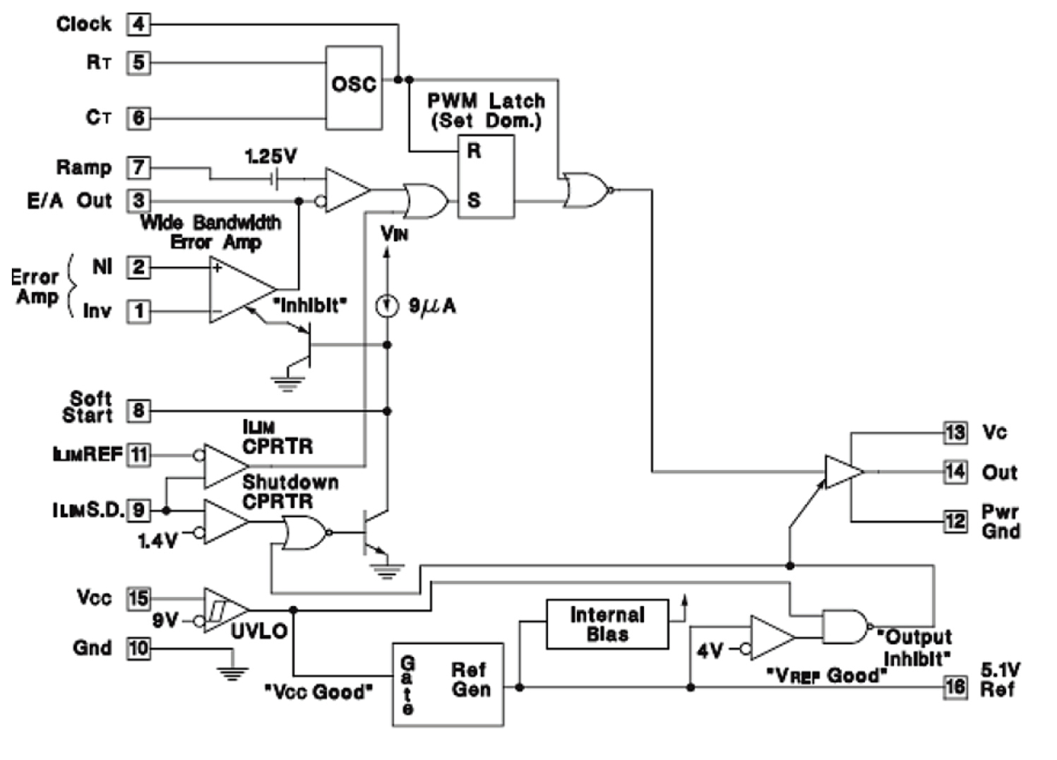
Keep The Ramp right
If the ramp driving your PWM-based controller is not linear, monotonic, or is simply noisy, your DC/DC converter will not perform optimally. It is essential to understand how to achieve the best performance from your system. A typical DC/DC power...