


Electric shaver motor drive circuit
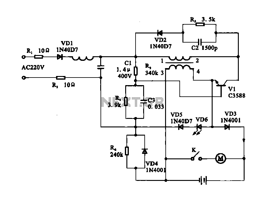
Description: Electric shaver motor drive circuit. It illustrates a typical motor drive circuit for an electric shaver. AC 220V is used to charge the battery through the charging circuit, which also provides power to the motor. After activating the charge-on switch K, the motor can operate.
The electric shaver motor drive circuit is designed to efficiently manage the charging and operation of the motor using an AC voltage of 220V. The circuit typically includes a rectifier to convert the AC input into a DC voltage suitable for battery charging. This rectified voltage is then regulated to ensure that the battery receives a stable and appropriate charging current, preventing overcharging and extending battery life.
The inclusion of a charge-on switch (K) allows the user to control the activation of the motor. When the switch is closed, it completes the circuit, enabling the power supply to the motor. The motor is often equipped with a controller or driver circuit to manage its speed and torque, ensuring optimal performance during operation.
Additional components may include fuses for overcurrent protection, capacitors for filtering and smoothing the power supply, and diodes for preventing back EMF generated by the motor from damaging the circuit. The design may also incorporate a thermal cutoff switch to protect against overheating, ensuring safety during prolonged use.
Overall, this circuit design emphasizes reliability and user control, making it suitable for use in consumer electric shavers, where performance and safety are paramount.Electric shaver motor drive circuit It shows a typical motor drive circuit of an electric shaver. AC 220V to charge the battery through the charging circuit, but also for the m otor power supply. After the charge-on switch K, the motor can work.
The electric shaver motor drive circuit is designed to efficiently manage the charging and operation of the motor using an AC voltage of 220V. The circuit typically includes a rectifier to convert the AC input into a DC voltage suitable for battery charging. This rectified voltage is then regulated to ensure that the battery receives a stable and appropriate charging current, preventing overcharging and extending battery life.
The inclusion of a charge-on switch (K) allows the user to control the activation of the motor. When the switch is closed, it completes the circuit, enabling the power supply to the motor. The motor is often equipped with a controller or driver circuit to manage its speed and torque, ensuring optimal performance during operation.
Additional components may include fuses for overcurrent protection, capacitors for filtering and smoothing the power supply, and diodes for preventing back EMF generated by the motor from damaging the circuit. The design may also incorporate a thermal cutoff switch to protect against overheating, ensuring safety during prolonged use.
Overall, this circuit design emphasizes reliability and user control, making it suitable for use in consumer electric shavers, where performance and safety are paramount.Electric shaver motor drive circuit It shows a typical motor drive circuit of an electric shaver. AC 220V to charge the battery through the charging circuit, but also for the m otor power supply. After the charge-on switch K, the motor can work.
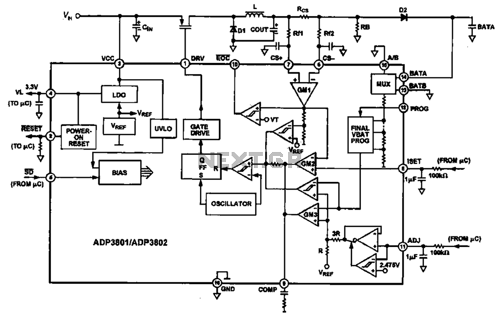
Charging circuit diagram personal work
Charging circuit diagram for personal work based on the operating principle of ADP3801/3802 charging circuit.
The ADP3801/3802 is a highly integrated battery charger controller designed for Li-ion and Li-polymer batteries. The charging circuit typically consists of several key components including the...
Charging circuit from the DC power supply switching power supply control
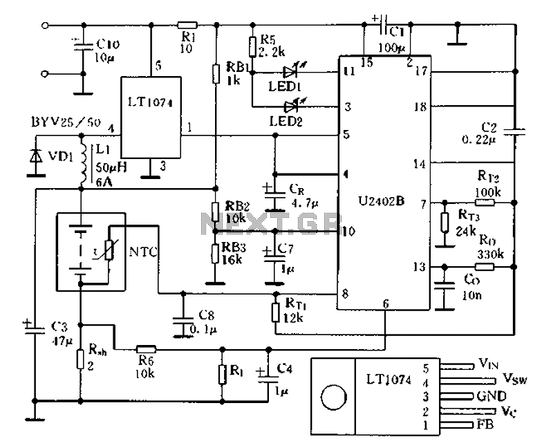
Charging circuit from the DC power supply switching power supply control
The charging circuit described is designed to operate with a DC power supply, utilizing a switching power supply control mechanism. This type of circuit is commonly employed in applications where...
battery charging indicator for
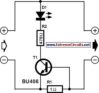
While owning a modern NiCd battery charger, there may still be instances where an incompatible battery is encountered, such as one with a unique voltage requirement or one that necessitates a higher charging current than what a standard charger can...
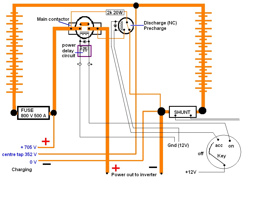
Split pack battery charging
A high voltage battery pack will be utilized in both the eCRX and the electric race bike.
A high voltage battery pack is a critical component in electric vehicles, providing the necessary energy storage to power electric motors effectively. In the...
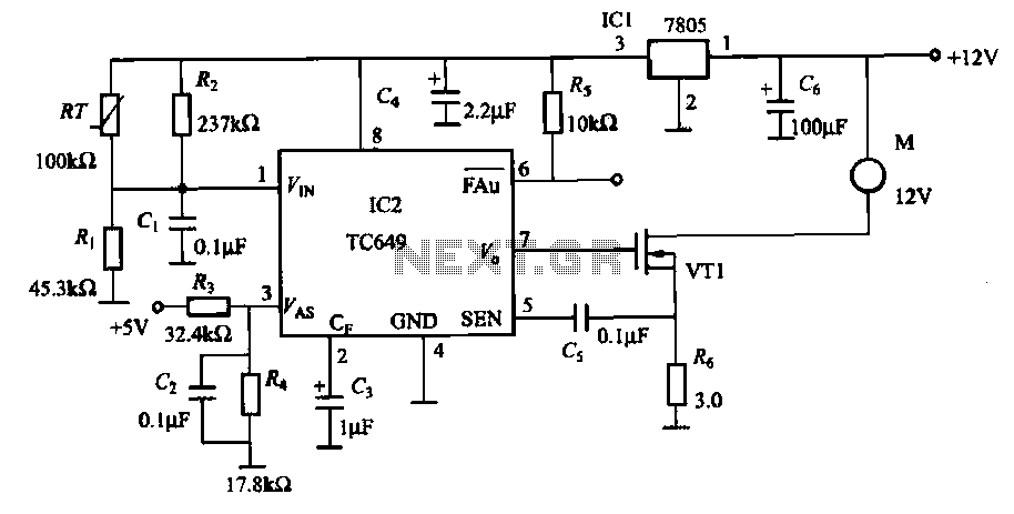
TC649 motor drive circuit with overheat protection
A motor is a heating device that can overheat, often due to accidents or overloads caused by excessive coil winding temperatures. The TC649 motor overheating protection and drive circuit, depicted in FIG. 1-9, utilizes an NTC thermistor (RT) positioned near...

One simple charging circuit b porcelain
After a slight loss of field strength, magnets can be re-magnetized using a simple homemade porcelain filler. Locate scrap materials such as switches and contacts, as well as other models like CJ10-60 ~ 15. The circuit can operate at 0A...
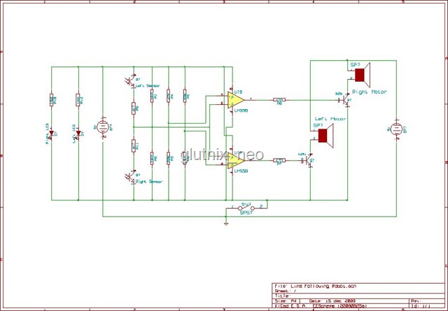
Simple MCU-less Differential Motor Drive Circuit
Originally, the tank cost around Php 400 but was later sold for approximately a hundred pesos less. Recognizing a great deal, the decision was made to purchase the toy. Opening the toy proved to be somewhat challenging. The track belt...
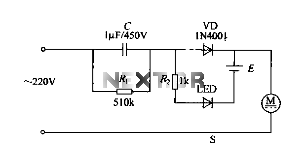
Electric shaver circuit
The electric shaver circuit is illustrated in Figure 1-17. It features a buck capacitor (C) rated at 1 µF and 450V, which connects through diode VD to charge 1.2V nickel-cadmium batteries. Additionally, after the buck converter, there is a display...