


For frequent motor starting Y- starting circuit
#motor starting
#Y-starting circuit
#contact KMi
#power failure
#motor transition
#industrial
#electrical
#control circuit
#three-phase motor
#starter
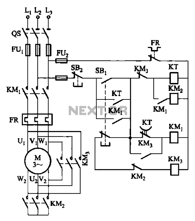
Description: The circuit depicted in Figure 3-41 illustrates a Y-transfer process. When contact KMi is turned off, the motor undergoes a transition in the event of a power failure. Additionally, the main contact KM3 is disconnected when KM2 is activated, ensuring that both cannot be in the ON state simultaneously. This design prevents frequent starts that may occur due to a short circuit fault.
The circuit functions as a motor control system that incorporates safety measures to enhance reliability during power fluctuations. The Y-transfer process indicates that the circuit is designed to manage the operational state of the motor effectively. When contact KMi is deactivated, it triggers a sequence that safely transitions the motor to a stop, thereby preventing damage from abrupt power loss.
The interlocking mechanism between KM2 and KM3 is a critical feature of this design. By ensuring that only one contact can be activated at a time, the circuit minimizes the risk of simultaneous engagement, which can lead to electrical faults or mechanical failures. This arrangement is particularly crucial in applications where motor control is sensitive to rapid cycling or where short circuits may occur.
The schematic would typically include various components such as relays, contactors, and possibly fuses to protect against overcurrent conditions. The design should also consider the ratings of the components to ensure they can handle the expected load and fault conditions. Implementing such a circuit requires careful attention to the specifications of each part, including coil voltages, contact ratings, and the overall configuration to ensure safe and efficient operation.
In summary, the circuit's design prioritizes safety and reliability, making it suitable for applications where power stability is a concern. The careful coordination between the contacts ensures that the motor operates within safe parameters, reducing the likelihood of damage from electrical faults. Circuit shown in Figure 3-41. This circuit Y- transfer process, contact KMi turned off again experienced a process of turning that motor is transitioned in case of power failur e; in addition, KM3 main contact is disconnected when KMz it can be turned on, the two can not simultaneously in the ON state, thereby avoiding frequent start due to a short circuit fault occurs.
The circuit functions as a motor control system that incorporates safety measures to enhance reliability during power fluctuations. The Y-transfer process indicates that the circuit is designed to manage the operational state of the motor effectively. When contact KMi is deactivated, it triggers a sequence that safely transitions the motor to a stop, thereby preventing damage from abrupt power loss.
The interlocking mechanism between KM2 and KM3 is a critical feature of this design. By ensuring that only one contact can be activated at a time, the circuit minimizes the risk of simultaneous engagement, which can lead to electrical faults or mechanical failures. This arrangement is particularly crucial in applications where motor control is sensitive to rapid cycling or where short circuits may occur.
The schematic would typically include various components such as relays, contactors, and possibly fuses to protect against overcurrent conditions. The design should also consider the ratings of the components to ensure they can handle the expected load and fault conditions. Implementing such a circuit requires careful attention to the specifications of each part, including coil voltages, contact ratings, and the overall configuration to ensure safe and efficient operation.
In summary, the circuit's design prioritizes safety and reliability, making it suitable for applications where power stability is a concern. The careful coordination between the contacts ensures that the motor operates within safe parameters, reducing the likelihood of damage from electrical faults. Circuit shown in Figure 3-41. This circuit Y- transfer process, contact KMi turned off again experienced a process of turning that motor is transitioned in case of power failur e; in addition, KM3 main contact is disconnected when KMz it can be turned on, the two can not simultaneously in the ON state, thereby avoiding frequent start due to a short circuit fault occurs.
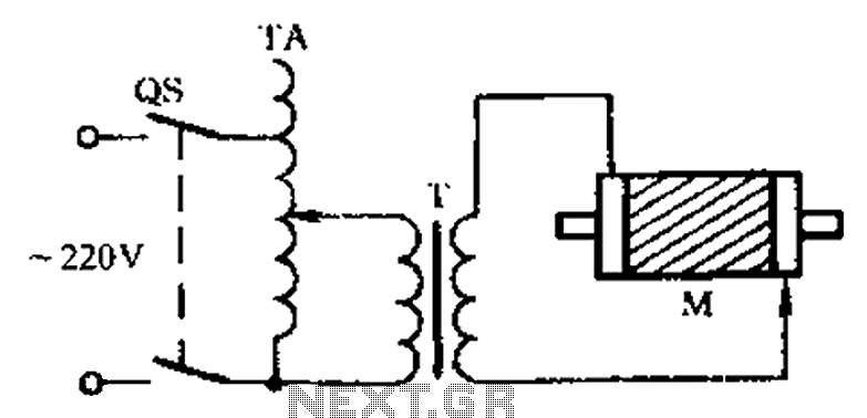
Check the three-phase motor with broken bars
The circuit diagram illustrates a three-phase motor equipped with an inspection circuit designed to detect broken bars.
The circuit for a three-phase motor with a broken bar inspection system typically consists of several key components that work together to monitor the...
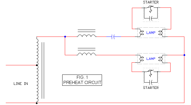
Preheat Ballast Schematic
It includes a starter for each lamp that heats the filaments (cathodes) at both ends of the lamp before ignition. Once the lamp is lit, the heated filaments are no longer necessary. The heating serves solely as an ignition aid....
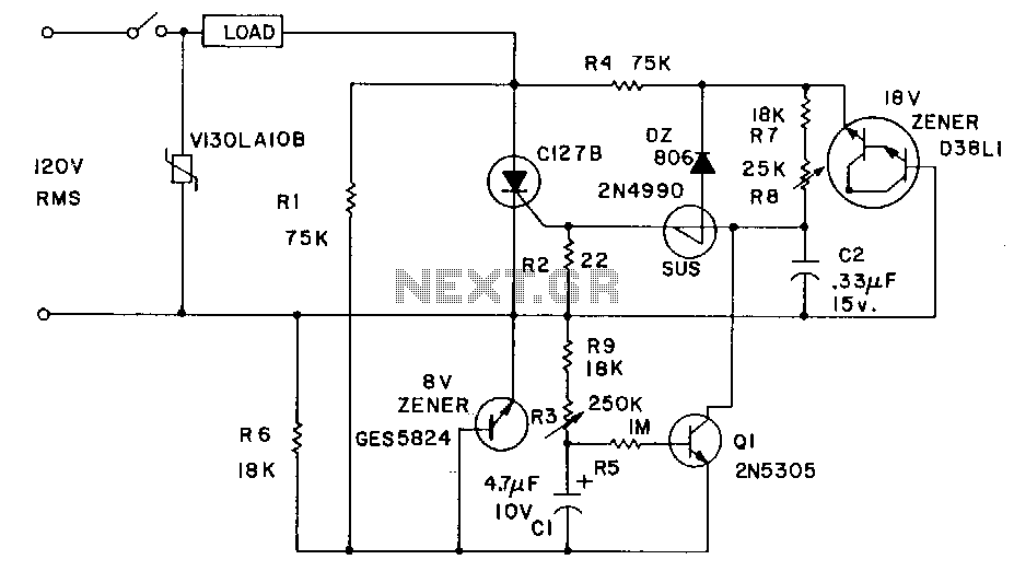
Burst-power-control
Industrial applications sometimes require that power be briefly applied to a load following the closure of a switch, such as a microswitch or foot switch. The load could be a heating element used for sealing plastic bags, a DC motor...

Three-phase squirrel cage motor running single phase connection circuit
The circuit connection is illustrated in figures a and b. In figure a, a star-shaped winding is used with shunt capacitance, while figure b depicts a triangular winding with capacitance connected in parallel. The working capacitance (Cc) is calculated using...
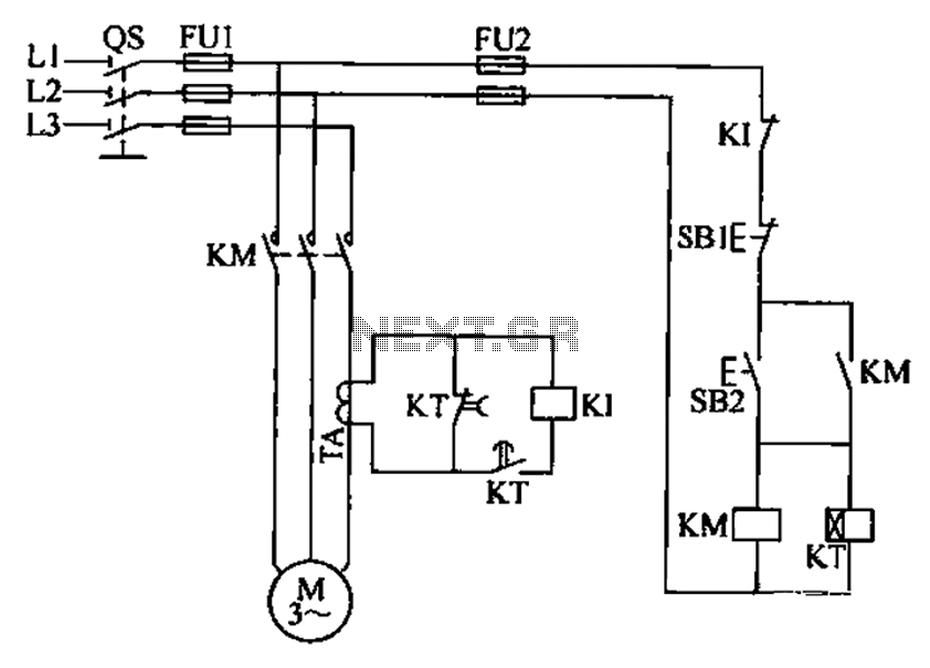
Three-phase motor overcurrent protection circuit
A three-phase electric motor overcurrent protection circuit. This example circuit utilizes a transformer to monitor the current, ensuring that the currents in the three-phase motor do not exceed normal operating levels. When the current exceeds the set threshold, the overcurrent...
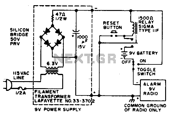
Power failure alarm
In the event of a power failure, the radio alarm activates without producing a loud siren, bell, or whistle. The alarm remains active even after power is restored and will continue until the RESET button is pressed.
The described circuit functions...
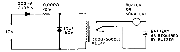
Power failure alarm
While the power is on, the relay remains open; however, when the power fails, the contacts of the buzzer circuit close.
The described circuit involves a relay and a buzzer, functioning in a power-dependent manner. In normal operation, when power is...
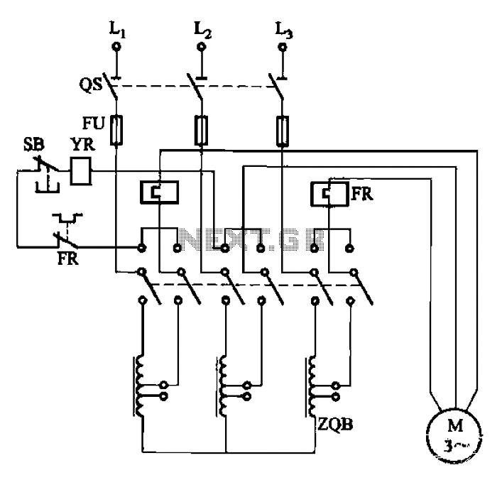
QJ3 series of manually operated auto-voltage start-up circuit
The circuit illustrated in Figure 3-47 involves a three-phase AC motor that is initially connected through a step-down autotransformer. To initiate operation, the power switch is closed, and the operating handle is pushed to the start position. Once the motor...
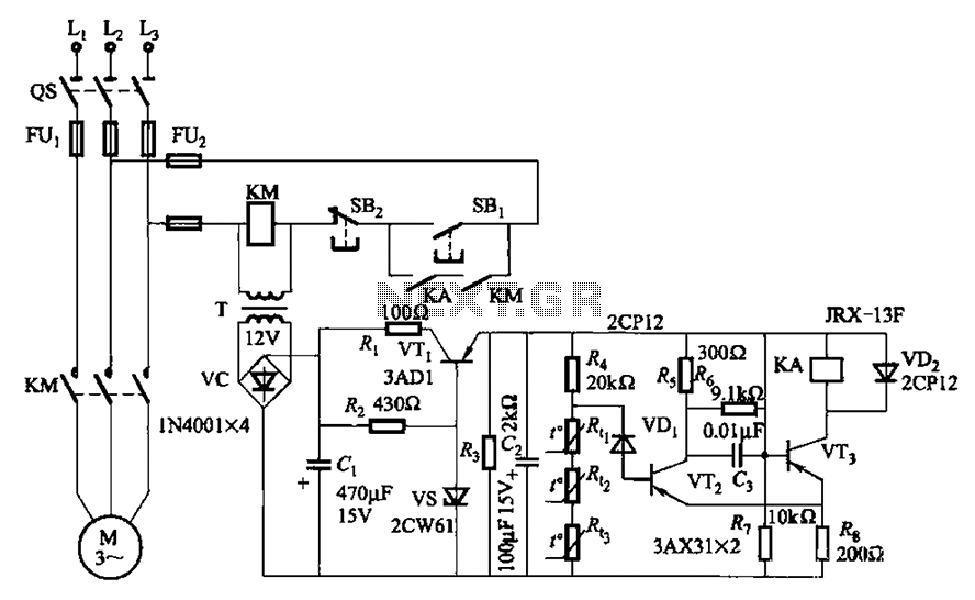
Three-phase asynchronous motor PTC protection circuits
A P-type transistor (VT2, VT3) and other components form a common emitter-coupled trigger, functioning as a Schmitt trigger device. This setup serves as a switching circuit to detect changes in the resistance of a PTC thermistor, thereby controlling the action...