


QJ3 series of manually operated auto-voltage start-up circuit
#three-phase motor
#autotransformer
#start-up circuit
#power switch
#AC motor
#manual control
#voltage regulation
#industrial
#electrical engineering
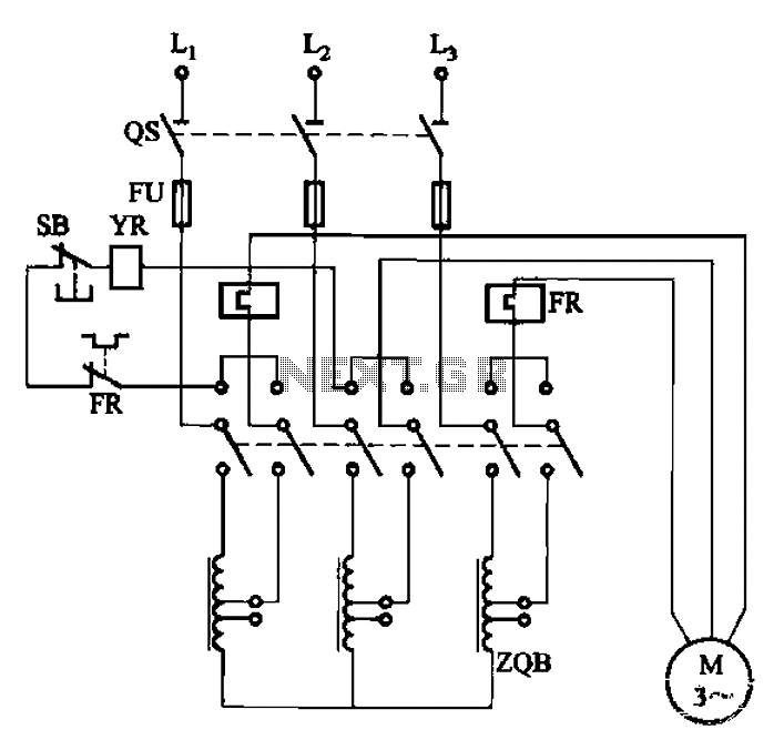
Description: The circuit illustrated in Figure 3-47 involves a three-phase AC motor that is initially connected through a step-down autotransformer. To initiate operation, the power switch is closed, and the operating handle is pushed to the start position. Once the motor has started, the operating handle is pulled to the Run position, which disengages the autotransformer voltage regulator, allowing the motor to connect directly to the three-phase power supply for full voltage operation. At this stage, the trip coil at the YR station is energized, maintaining the operating handle in the Run position through an interlocking mechanism. To stop the motor, the stop button (SB) can be pressed.
This circuit design utilizes a step-down autotransformer to facilitate a soft start for the three-phase AC motor, which is particularly beneficial for reducing inrush currents and mechanical stress on the motor during startup. The autotransformer allows for a lower voltage to be applied initially, ensuring a gradual ramp-up to full operational speed.
The interlocking mechanism is a critical safety feature that prevents accidental disconnection of the motor while it is running. This mechanism ensures that as long as the motor is energized, the operating handle remains locked in the Run position, thereby preventing any unintentional stop commands that could lead to operational hazards. The trip coil serves as an actuator that maintains this lock, ensuring operational safety.
When the motor needs to be stopped, the stop button (SB) can be pressed, which will deactivate the trip coil and release the interlocking mechanism, allowing the operating handle to return to a neutral position. This design ensures that the motor can be safely and effectively controlled, providing both operational efficiency and safety for users.
Overall, this circuit configuration is well-suited for applications requiring controlled motor startup and reliable operational management, making it a valuable addition to industrial motor control systems. Circuit shown in Figure 3-47. Close the power switch os, operating handle to push the start position, then three-phase AC motor is connected through a step-down autotransformer after. To be started is completed, the operating handle to pull the Run position, autotransformer voltage regulator out of operation, the motor directly connected to the three-phase power supply for full voltage operation. At this time the trip coil is energized YR station, keeping the operating handle in the operating position by the interlocking mechanism.
When stop, press the stop button SB can.
This circuit design utilizes a step-down autotransformer to facilitate a soft start for the three-phase AC motor, which is particularly beneficial for reducing inrush currents and mechanical stress on the motor during startup. The autotransformer allows for a lower voltage to be applied initially, ensuring a gradual ramp-up to full operational speed.
The interlocking mechanism is a critical safety feature that prevents accidental disconnection of the motor while it is running. This mechanism ensures that as long as the motor is energized, the operating handle remains locked in the Run position, thereby preventing any unintentional stop commands that could lead to operational hazards. The trip coil serves as an actuator that maintains this lock, ensuring operational safety.
When the motor needs to be stopped, the stop button (SB) can be pressed, which will deactivate the trip coil and release the interlocking mechanism, allowing the operating handle to return to a neutral position. This design ensures that the motor can be safely and effectively controlled, providing both operational efficiency and safety for users.
Overall, this circuit configuration is well-suited for applications requiring controlled motor startup and reliable operational management, making it a valuable addition to industrial motor control systems. Circuit shown in Figure 3-47. Close the power switch os, operating handle to push the start position, then three-phase AC motor is connected through a step-down autotransformer after. To be started is completed, the operating handle to pull the Run position, autotransformer voltage regulator out of operation, the motor directly connected to the three-phase power supply for full voltage operation. At this time the trip coil is energized YR station, keeping the operating handle in the operating position by the interlocking mechanism.
When stop, press the stop button SB can.
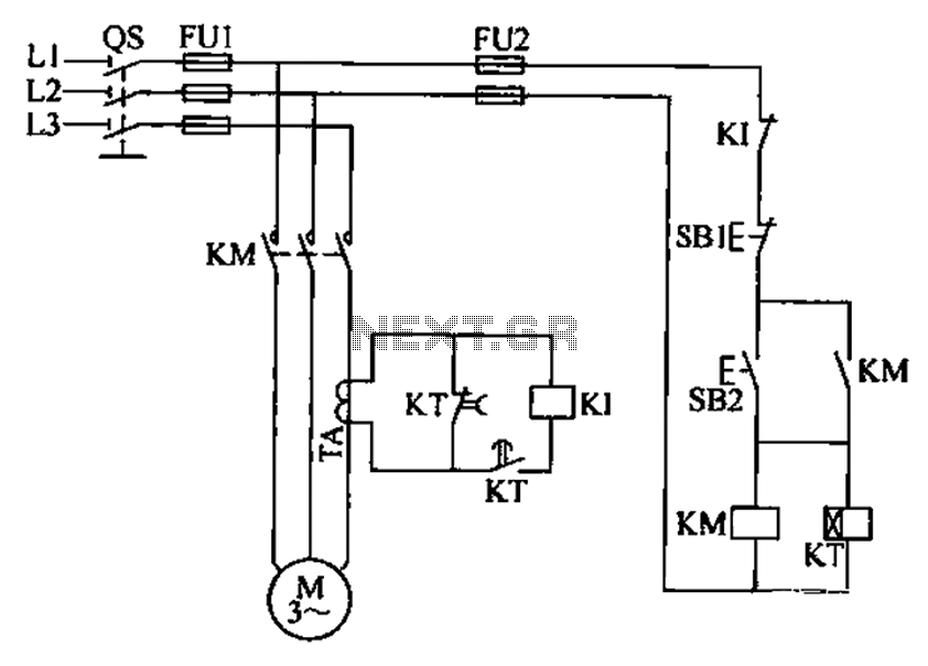
Three-phase motor overcurrent protection circuit
A three-phase electric motor overcurrent protection circuit. This example circuit utilizes a transformer to monitor the current, ensuring that the currents in the three-phase motor do not exceed normal operating levels. When the current exceeds the set threshold, the overcurrent...
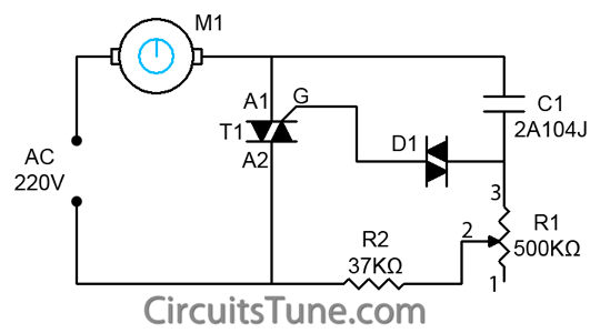
ceiling fan regulator motor speed
This is a simple ceiling fan regulator circuit diagram used to control the speed of a ceiling fan. In other words, it is an AC motor speed controller circuit that regulates the speed of an AC motor (ceiling fan). This...
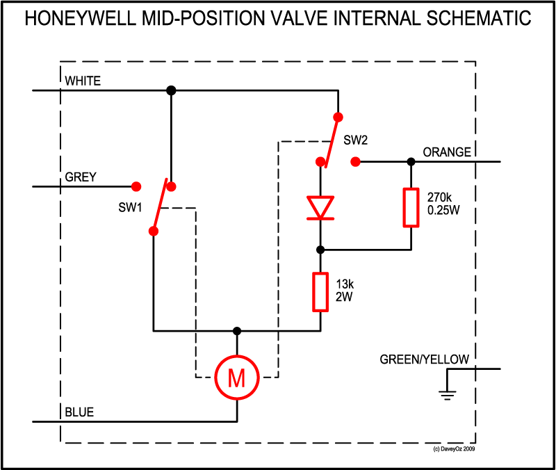
mid position valve
The three-port valve is an innovative engineering solution that operates in one of three positions using a non-reversible AC motor, a spring, a couple of micro-switches, a resistor, and a diode, while also functioning as a relay for the boiler....
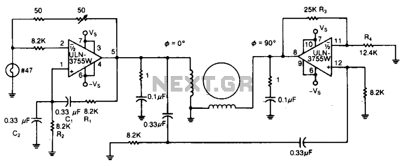
Two-phase ac motor driver
Due to its high amplification factor and integrated power-output stage, an integrated power operational amplifier serves as an effective driver for AC motors. One operational amplifier can be configured as an oscillator to generate the necessary AC signal. The power-output...
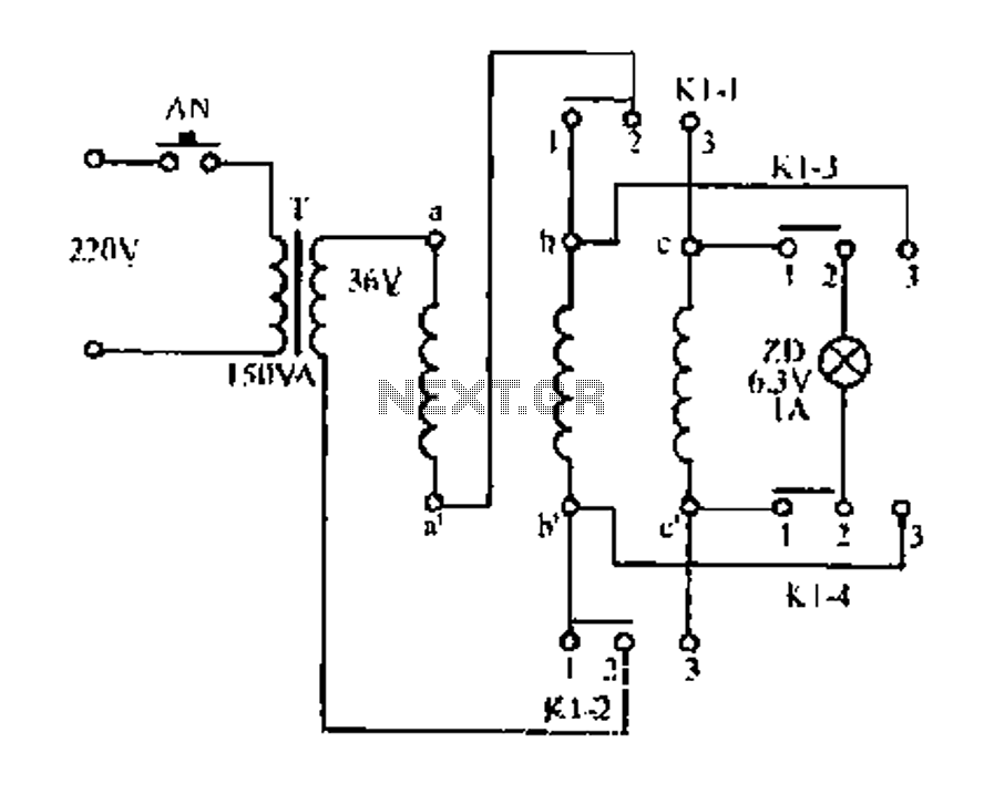
The beginning and end of a three-phase motor winding speed judgment circuit
Figure aa, bb, and ce represent three-phase windings. A double throw switch Kl-1 to Kl-4 is positioned on the left side, connecting phases 1 and 2. At this point, aa and bb are in series with the secondary of transformer...
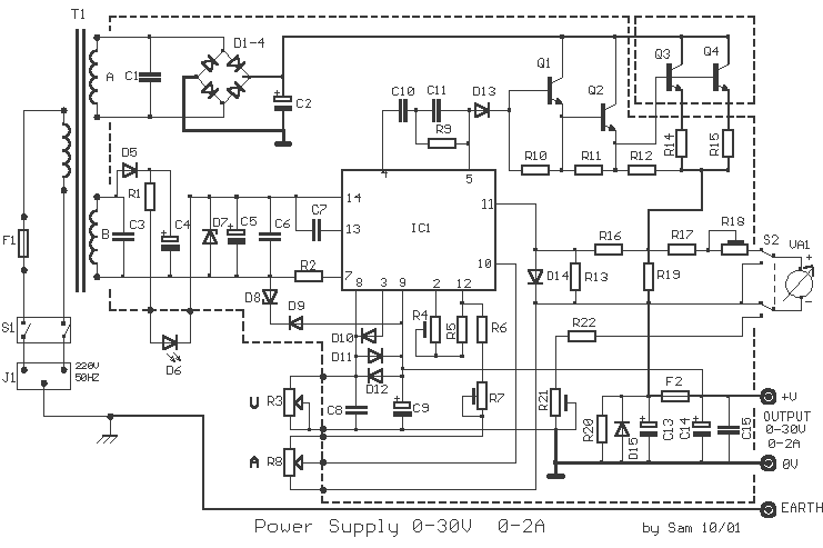
Power Supply 0-30V / 0-2A
The basic requirements for a laboratory power supply are to provide the necessary voltages and currents with low output resistance, low noise, minimal ripple, and good stabilization. These requirements are addressed within the circuit design. Many power supplies incorporate electronic...
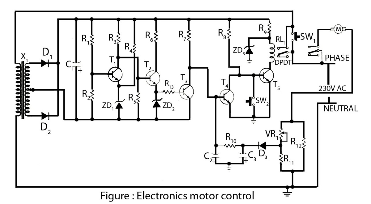
Electronics Motor Controller AC Motor
Electronics motor control is a simple circuit made without an integrated circuit (IC). It involves the electronic control of an AC motor and includes a circuit diagram along with a description of the electronics motor controller.
The electronics motor control circuit...
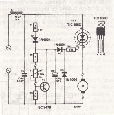
AC Drill Speed Controller Circuit
This AC drill speed controller circuit schematic allows for the control of the drilling speed of a borer or drilling machine. This project is based on the principle that...
The AC drill speed controller circuit is designed to modulate the speed...
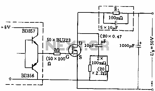
500A power switch control circuit diagram
The circuit employs 50 BUZ23 field effect transistors (FETs) arranged in parallel, with a tube blocking voltage of 100V. The control power required is minimal, eliminating the risks associated with second breakdown and the positive temperature coefficient phenomenon in the...