


PPMC and stepping motor driver IC dedicated connection circuit
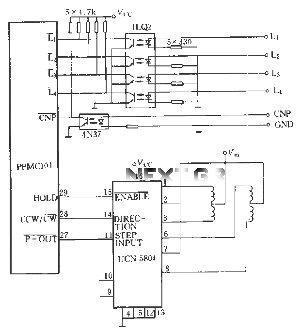
Description: The PPMC external UChl 5804 demonstrates a four-phase stepping motor drive integrated circuit (IC) that is depicted in a downward motion. It utilizes the P-OUT, counterclockwise (ccw) / clockwise (cw), and HOLD outputs. The UCN5804 pins 9 and 10 can be configured for a two-phase motor tuning step, single-phase full-step, half-step, and other operational modes in three distinct configurations. The accompanying figure illustrates the optocoupler connection linking five limit switches to the PPMC.
The PPMC external UChl 5804 is designed to control a four-phase stepping motor through a series of outputs that facilitate various operational modes. The P-OUT output serves as the primary control signal for the motor, while the ccw and cw outputs determine the rotational direction of the motor. The HOLD output is utilized to maintain the motor's position when not actively stepping, reducing power consumption and preventing unwanted movement.
The UCN5804 integrated circuit is a versatile component that supports multiple configurations for motor operation. By employing pins 9 and 10, the circuit can be adjusted to operate in a two-phase tuning step mode, which allows for finer control of the motor's position and speed. Additionally, the IC can be configured for single-phase full-step and half-step modes, providing flexibility in the motor's performance based on the application's requirements.
The schematic includes an optocoupler connection to five limit switches, which are critical for ensuring that the motor does not exceed its designated range of motion. The limit switches provide feedback to the control system, enabling it to stop the motor when it reaches a predefined position. This integration enhances the safety and reliability of the system, preventing damage to the motor and associated components.
Overall, the PPMC external UChl 5804 and its associated circuitry represent a sophisticated approach to controlling stepping motors, offering a range of operational modes and safety features that are essential for precise motor control in various applications.PPMC external UChl 5804 shows four-phase stepping motor drive IC is shown moving down. It uses the P-OUT, ccw / cw and HOLD output. Use UCN5804 9 and 10 pin logic level can be set up as a two-phase motor tuning step, single-phase full-step, half-step and other incentives in three different sports. In this figure, it was shown by the optocoupler connection between the five limit switches and PPMC.
The PPMC external UChl 5804 is designed to control a four-phase stepping motor through a series of outputs that facilitate various operational modes. The P-OUT output serves as the primary control signal for the motor, while the ccw and cw outputs determine the rotational direction of the motor. The HOLD output is utilized to maintain the motor's position when not actively stepping, reducing power consumption and preventing unwanted movement.
The UCN5804 integrated circuit is a versatile component that supports multiple configurations for motor operation. By employing pins 9 and 10, the circuit can be adjusted to operate in a two-phase tuning step mode, which allows for finer control of the motor's position and speed. Additionally, the IC can be configured for single-phase full-step and half-step modes, providing flexibility in the motor's performance based on the application's requirements.
The schematic includes an optocoupler connection to five limit switches, which are critical for ensuring that the motor does not exceed its designated range of motion. The limit switches provide feedback to the control system, enabling it to stop the motor when it reaches a predefined position. This integration enhances the safety and reliability of the system, preventing damage to the motor and associated components.
Overall, the PPMC external UChl 5804 and its associated circuitry represent a sophisticated approach to controlling stepping motors, offering a range of operational modes and safety features that are essential for precise motor control in various applications.PPMC external UChl 5804 shows four-phase stepping motor drive IC is shown moving down. It uses the P-OUT, ccw / cw and HOLD output. Use UCN5804 9 and 10 pin logic level can be set up as a two-phase motor tuning step, single-phase full-step, half-step and other incentives in three different sports. In this figure, it was shown by the optocoupler connection between the five limit switches and PPMC.
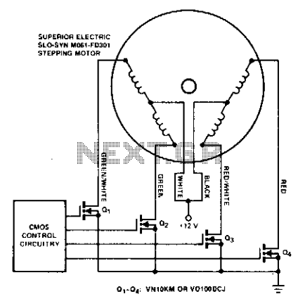
Stepping motor driver
Stepping motors are commonly utilized in disk drives and machine control applications. MOSPOWER transistors serve as excellent motor drivers due to their immunity to second breakdown. It is important to note that snubbing networks are unnecessary since load line shaping...
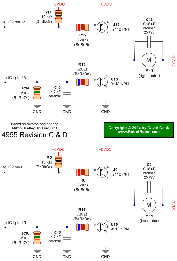
Big Trak Motor Driver Schematic
Schematic of Big Trak's motor driver circuit. The toy includes 9112 and 9113 transistors (and sometimes 2N6715) because the 75494 chip cannot supply enough current to run the Big Trak's motors by itself.
The motor driver circuit for the Big Trak...
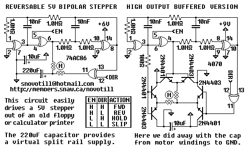
Stepping Motor Driver
The circuit is not particularly susceptible to motor transients and supports FULL STEPS FORWARD, FULL STEPS REVERSE, ACTIVE HOLD, and POWER OFF aka RELEASED. If the motor does not turn then swap around the leads of ONE of the two...
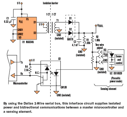
Add Ramp To Stepping Motor
Stepping motor controllers are frequently preferred over complex software-driven controllers due to their low cost. However, stepping motors tend to exhibit low torque at high speeds, necessitating a starting ramp to avoid stalling during startup. This circuit provides a one-chip...

Music Driven Motor Schematic
Music Driven Motor Schematic. The geared motor drives the stem of a dancing flower to the beat of music.
The music-driven motor schematic involves a geared motor that is activated in response to sound signals, specifically music. This design typically incorporates...
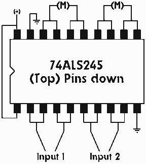
Single IC chip Motor Driver for robots
A motor driver is required in pretty much all walkers including all of my CW series walkers. You need to use it any time you need to supply more current to the motors because the circuit can't supply enough. This...
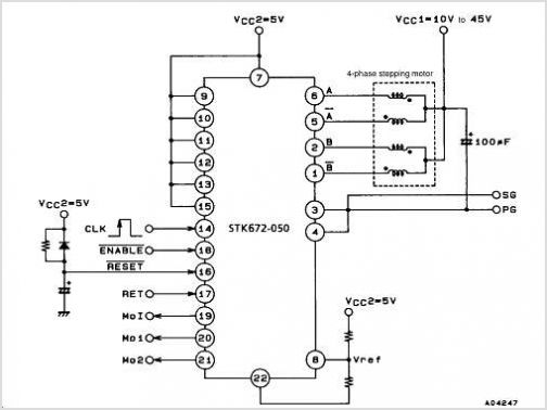
STK672-050 Microstep Operation-supported 4-phase Stepping Motor Driver (io= 3.0a) Semicon Device
The STM1061 low power voltage detector monitors battery, power supply, and regulated system voltages. A precision voltage reference and comparator assess the V_CC input, comparing it with a specified voltage threshold. When V_CC falls below the defined trip point threshold,...
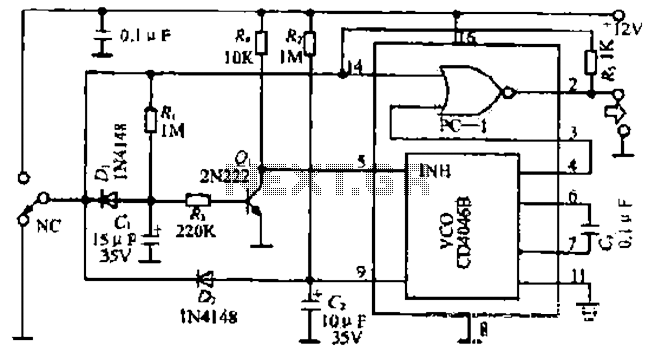
Rapid control circuit of a stepping motor
The figure illustrates a circuit involving dark tomb electric locks, specifically the fti: al: 4046B and XOR gate as the primary control mechanism. It emits pulses and utilizes silicon for successive pulse generation. The circuit operates with a normal button...
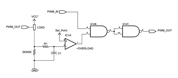
Custom Motor Driver
This chapter was removed from Applied Robotics 2 due to space constraints. It addresses general motor control issues and details the construction of a 5-amp motor driver. The principles discussed can be applied to larger motor controllers. Although commercially available...