


PQY1 series magnetic disk control circuit control
#magnetic disk control
#master controller
#control panel
#limit switch
#motor driver
#reverse limit
#LK16-5/31
#PQY1 series
#industrial control
#automation

Description: The system consists of an LK16-5/31 type master controller and a PQY1 Series magnetic control panel, which includes a control circuit. The motor is controlled by limit switches SQ1 and SQ2, which manage the reverse operation. The master controller handle (SA) features seven positions, including a zero position, three positions for upward movement, and three positions for downward movement. Additionally, there are modes for both organic mechanical parking brake and reverse parking brake.
The LK16-5/31 master controller serves as the primary interface for the operator, allowing for precise control of the motor's operation through its various positions. Each of the seven handle positions corresponds to specific operational states, facilitating efficient management of the motor's direction and speed. The three upward positions enable the motor to perform lifting actions, while the three downward positions allow for controlled descent. The zero position acts as a neutral state, ensuring that the motor is deactivated when not in use.
The inclusion of limit switches SQ1 and SQ2 is crucial for ensuring safe operation. These switches detect the motor's position and prevent it from exceeding predetermined limits. When the motor reaches the upper or lower limit, the corresponding switch is activated, signaling the controller to halt the motor's movement, thereby preventing mechanical damage or failure.
The PQY1 Series magnetic control panel complements the master controller by providing additional functionality and safety features. It is designed to handle the electrical connections and control signals necessary for the operation of the motor and its associated components. The panel's layout is optimized for ease of use and accessibility, allowing operators to monitor and adjust settings quickly.
Furthermore, the system's parking brake modes enhance safety during operation. The organic mechanical parking brake mode engages a traditional mechanical brake system, ensuring the motor remains stationary when not in operation. The reverse parking brake mode provides an additional layer of safety by preventing unintended movement when the motor is in reverse, thereby protecting both the equipment and the operator.
Overall, this comprehensive control system is designed to ensure reliable and safe operation of the motor, with multiple features aimed at enhancing user control and preventing accidents. By LK16-5/31 type master controller and PQY1 Series Magnetic control panel consisting of a control circuit. Figure, SQ1, SQ2 the motor is, reverse limit switch. Master controll er handle SA has seven positions, in addition to the zero position, there are three rose and three fell block block. In addition to organic mechanical parking brake mode, there are reverse parking brake mode.
The LK16-5/31 master controller serves as the primary interface for the operator, allowing for precise control of the motor's operation through its various positions. Each of the seven handle positions corresponds to specific operational states, facilitating efficient management of the motor's direction and speed. The three upward positions enable the motor to perform lifting actions, while the three downward positions allow for controlled descent. The zero position acts as a neutral state, ensuring that the motor is deactivated when not in use.
The inclusion of limit switches SQ1 and SQ2 is crucial for ensuring safe operation. These switches detect the motor's position and prevent it from exceeding predetermined limits. When the motor reaches the upper or lower limit, the corresponding switch is activated, signaling the controller to halt the motor's movement, thereby preventing mechanical damage or failure.
The PQY1 Series magnetic control panel complements the master controller by providing additional functionality and safety features. It is designed to handle the electrical connections and control signals necessary for the operation of the motor and its associated components. The panel's layout is optimized for ease of use and accessibility, allowing operators to monitor and adjust settings quickly.
Furthermore, the system's parking brake modes enhance safety during operation. The organic mechanical parking brake mode engages a traditional mechanical brake system, ensuring the motor remains stationary when not in operation. The reverse parking brake mode provides an additional layer of safety by preventing unintended movement when the motor is in reverse, thereby protecting both the equipment and the operator.
Overall, this comprehensive control system is designed to ensure reliable and safe operation of the motor, with multiple features aimed at enhancing user control and preventing accidents. By LK16-5/31 type master controller and PQY1 Series Magnetic control panel consisting of a control circuit. Figure, SQ1, SQ2 the motor is, reverse limit switch. Master controll er handle SA has seven positions, in addition to the zero position, there are three rose and three fell block block. In addition to organic mechanical parking brake mode, there are reverse parking brake mode.
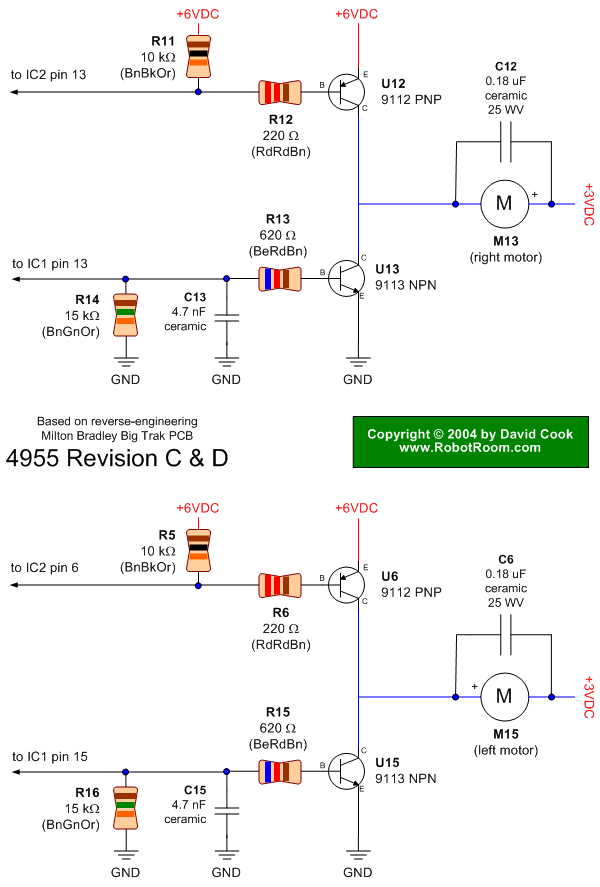
Big Trak Motor Driver Schematic
Schematic of Big Trak's motor driver circuit. The toy includes 9112 and 9113 transistors (and sometimes 2N6715) because the 75494 chip cannot supply enough current to run the Big Trak's motors by itself.
The motor driver circuit for the Big Trak...
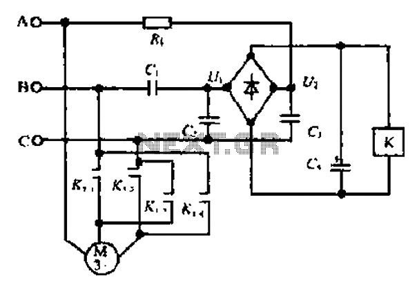
A motor reversing automatic adjustment circuit
Composition ratio circuit. The circuit consists of resistors and capacitors that form a shift register circuit with diodes VD1 to VD4, creating a bridge for electric current. Capacitor C4 is utilized for filtering applications and for eliminating instantaneous relay energization...
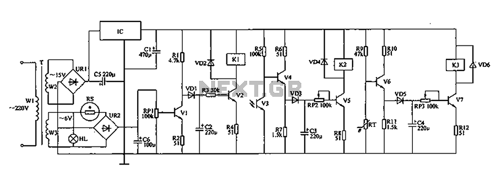
Coop automatic controller circuit diagram
The automatic controller for a chicken coop is designed to automatically regulate light, temperature, and humidity, thereby enhancing egg production and survival rates of chickens. This device is intended for specialized poultry households in rural areas. The circuit operates through...
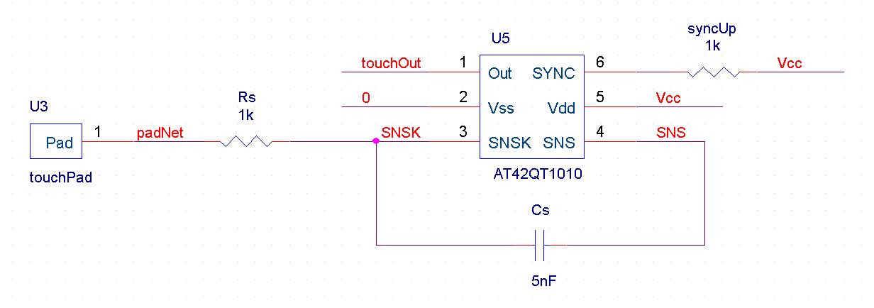
automatic pet feeder
An automatic feeder dispenses food based on the activation of a series of buttons, which interface with a system controller and a food dispenser. The system is designed for intelligent processing of inputs and outputs, allowing dynamic configuration of button...

Music Driven Motor Schematic
Music Driven Motor Schematic. The geared motor drives the stem of a dancing flower to the beat of music.
The music-driven motor schematic involves a geared motor that is activated in response to sound signals, specifically music. This design typically incorporates...
Big Trak Motor Driver Schematic
Schematic of Big Trak's motor driver circuit. The toy includes 9112 and 9113 transistors (and sometimes 2N6715) because the 75494 chip cannot supply enough current to run the Big Trak's motors by itself.
The motor driver circuit for the Big Trak...
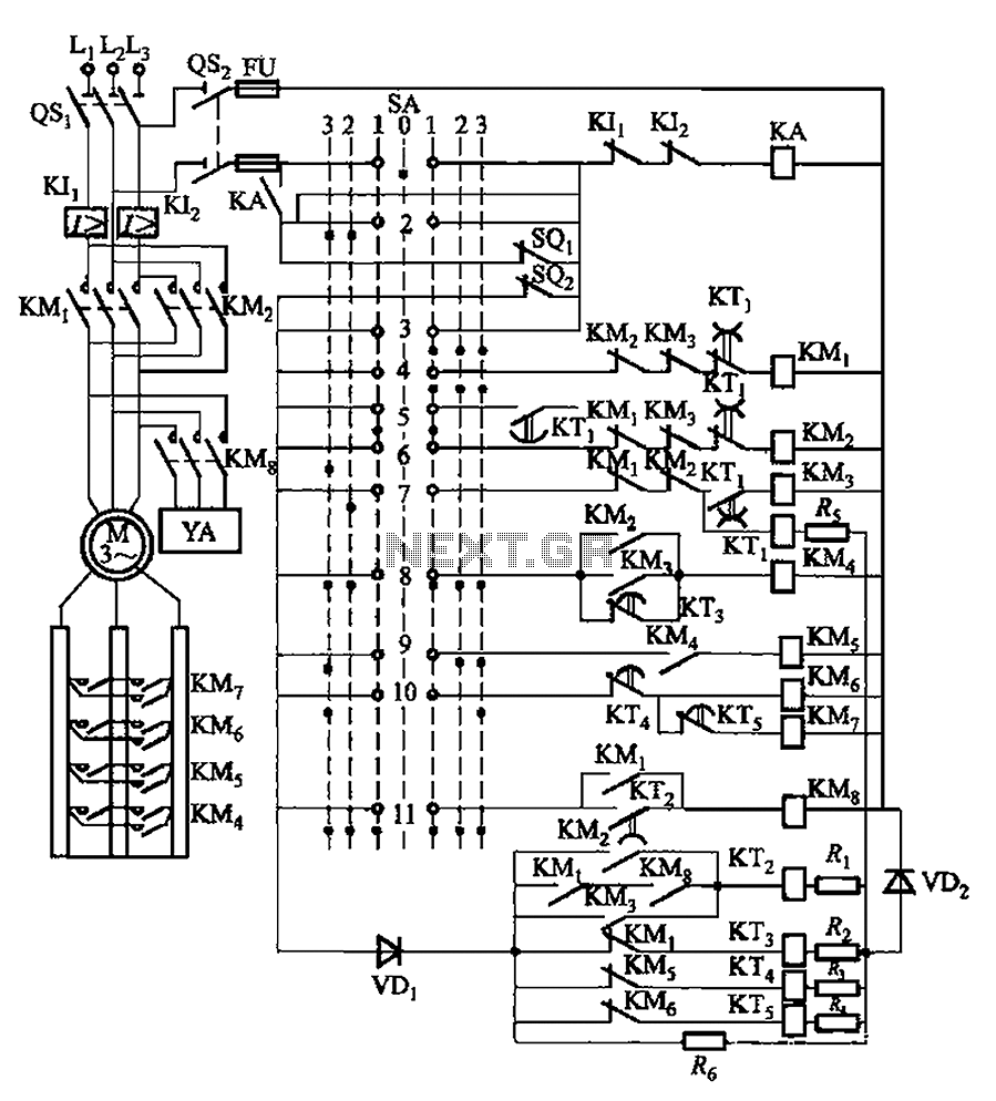
PQS1 series magnetic disk control panning control circuit
The system involves a master controller and a PQS1 Series Magnetic control panel, which includes a control circuit designed to manage the bridge crane hoist lifting mechanism. The master controller handle SA features seven positions: alongside the zero position, it...
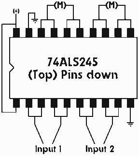
Single IC chip Motor Driver for robots
A motor driver is required in pretty much all walkers including all of my CW series walkers. You need to use it any time you need to supply more current to the motors because the circuit can't supply enough. This...
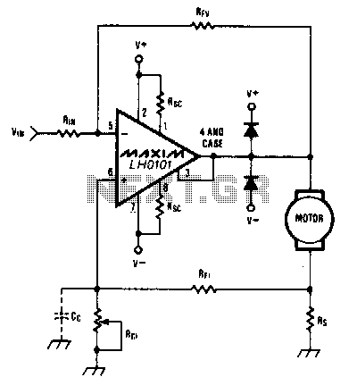
Constant-speed-motor-driver
When the torque load on the motor increases, its current also rises. This increase in current is detected across Rs, and positive feedback is applied to the noninverting terminal of the LH0101, which in turn raises the motor voltage to...