


QX1 QX2 series magnetic starter Y- reduced-voltage starting circuit
#magnetic starter
#reduced-voltage starting
#three-phase
#stator windings
#contact closure
#motor terminal
#starter
#circuit diagram
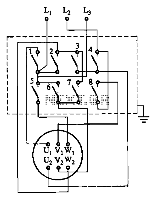
Description: The circuit illustrated in Figure 3-36 includes the starter contact closure detailed in Table 3-1. In the figure, U1, V1, W1, and U2, V2, W2 represent the first three-phase stator windings of the motor terminals.
The circuit depicted in Figure 3-36 is a critical component of a three-phase motor control system. It demonstrates the configuration of the starter contact closure, which is essential for initiating the motor operation. The motor's stator windings are represented as U1, V1, W1 for the first set and U2, V2, W2 for the second set, indicating the dual winding arrangement typical in three-phase motors.
The starter contact closure, as referenced in Table 3-1, provides a systematic approach to energizing the motor. This closure is responsible for completing the circuit and allowing current to flow through the stator windings, which generates a rotating magnetic field necessary for motor operation. The interaction between the stator windings and the rotor creates torque, enabling the motor to perform work.
In practical applications, the design and layout of the circuit must ensure that the starter contacts are rated appropriately for the motor's operational current and voltage. It is also essential to incorporate protective elements such as fuses or circuit breakers to prevent damage to the motor and associated circuitry in the event of overloads or short circuits.
Furthermore, attention should be given to the phase sequence of the stator windings, as incorrect phasing can lead to reverse rotation of the motor. Proper labeling and connection of terminals U1, V1, W1, U2, V2, and W2 are crucial to maintain the correct operational parameters and ensure reliable performance of the motor system.
Overall, the configuration shown in Figure 3-36 is foundational for understanding the operation of three-phase motors and their control mechanisms, highlighting the importance of precise electrical connections and protective measures in motor applications. Circuit shown in Figure 3-36. Starter contact closure is shown in table 3-1. Figure, Ul, Vi, wl and U2, vz, W2 are the first three-phase stator windings of the motor terminal.
The circuit depicted in Figure 3-36 is a critical component of a three-phase motor control system. It demonstrates the configuration of the starter contact closure, which is essential for initiating the motor operation. The motor's stator windings are represented as U1, V1, W1 for the first set and U2, V2, W2 for the second set, indicating the dual winding arrangement typical in three-phase motors.
The starter contact closure, as referenced in Table 3-1, provides a systematic approach to energizing the motor. This closure is responsible for completing the circuit and allowing current to flow through the stator windings, which generates a rotating magnetic field necessary for motor operation. The interaction between the stator windings and the rotor creates torque, enabling the motor to perform work.
In practical applications, the design and layout of the circuit must ensure that the starter contacts are rated appropriately for the motor's operational current and voltage. It is also essential to incorporate protective elements such as fuses or circuit breakers to prevent damage to the motor and associated circuitry in the event of overloads or short circuits.
Furthermore, attention should be given to the phase sequence of the stator windings, as incorrect phasing can lead to reverse rotation of the motor. Proper labeling and connection of terminals U1, V1, W1, U2, V2, and W2 are crucial to maintain the correct operational parameters and ensure reliable performance of the motor system.
Overall, the configuration shown in Figure 3-36 is foundational for understanding the operation of three-phase motors and their control mechanisms, highlighting the importance of precise electrical connections and protective measures in motor applications. Circuit shown in Figure 3-36. Starter contact closure is shown in table 3-1. Figure, Ul, Vi, wl and U2, vz, W2 are the first three-phase stator windings of the motor terminal.
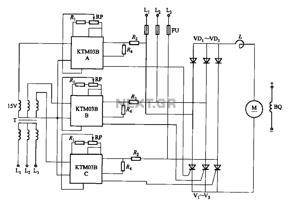
KTM03 type speed control for three-phase half-controlled rectifier circuit
Adjusting the phase potentiometer RP can change the conduction angle of each corresponding thyristor (V1-V). This adjustment alters the voltage applied across the load.
The circuit utilizes a phase control technique to manage the power delivered to a load by varying...
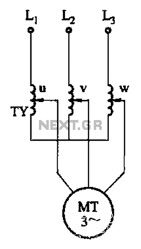
Three phase torque motor speed control circuit
The circuit depicted in Figure 3-176 illustrates an adjustment method that allows the motor to operate at equilibrium. The adjustment range is relatively wide; however, it necessitates a three-phase voltage regulator, which incurs higher input costs.
The circuit design in Figure...
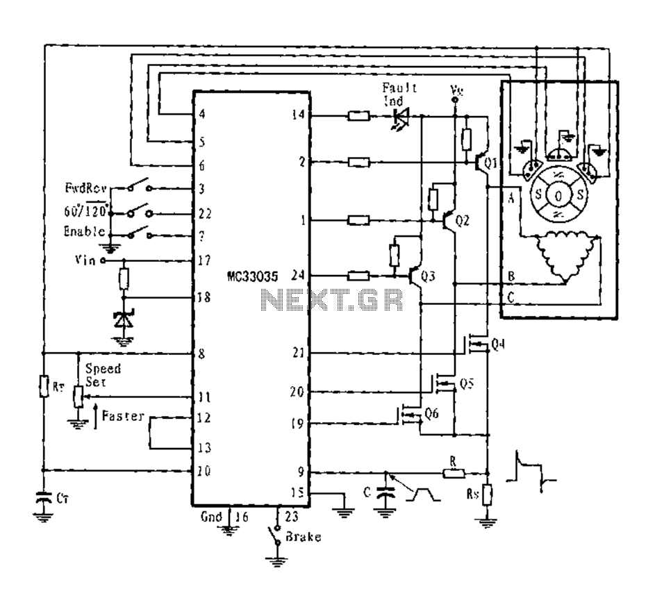
Three-phase six-step motor control circuit diagram composed of MC33035
The application circuit is a three-phase full-wave six-step driving circuit for an open-loop motor controller. It features a power switching transistor of the Darlington type, specifically PNP, while the lower power switching transistors are N-channel power MOSFETs. Each device incorporates...
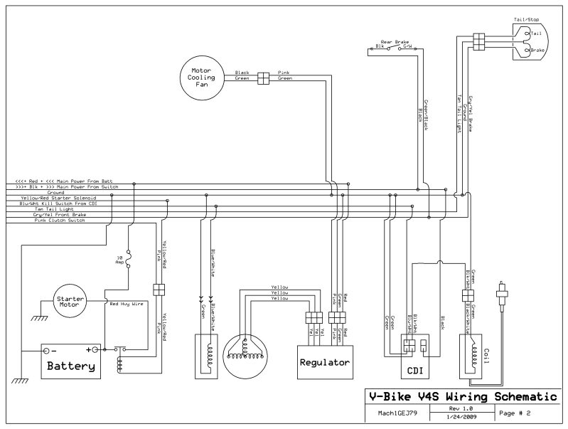
help diagnose stator
A 2005 Wildfire 250 QAC ATV is experiencing starting issues. When attempting to start, it sounds as though the starter gears are spinning without engaging. After flipping the ATV, the problem has persisted. There is a one-way clutch between the...
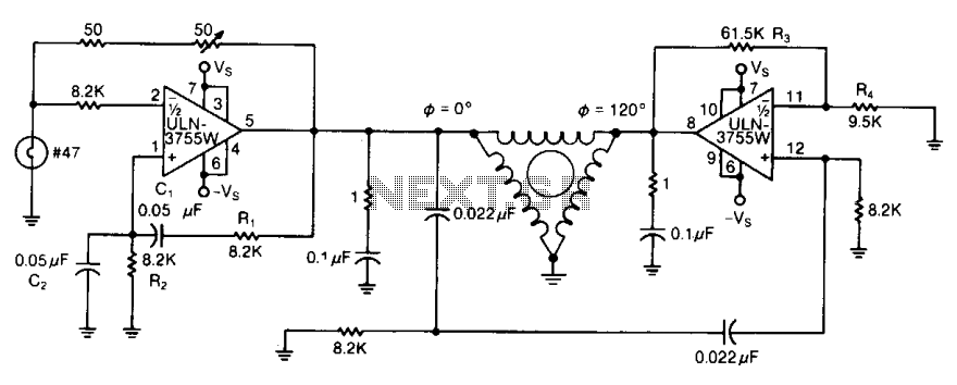
Three-phase ac motor driver 2
By varying either R1 or R2, the oscillator frequency can be adjusted over a narrow range. The R3/R4 ratio sets the second amplifier's gain to compensate for signal attenuation occurring in the phase shifters. The circuits can be driven from...
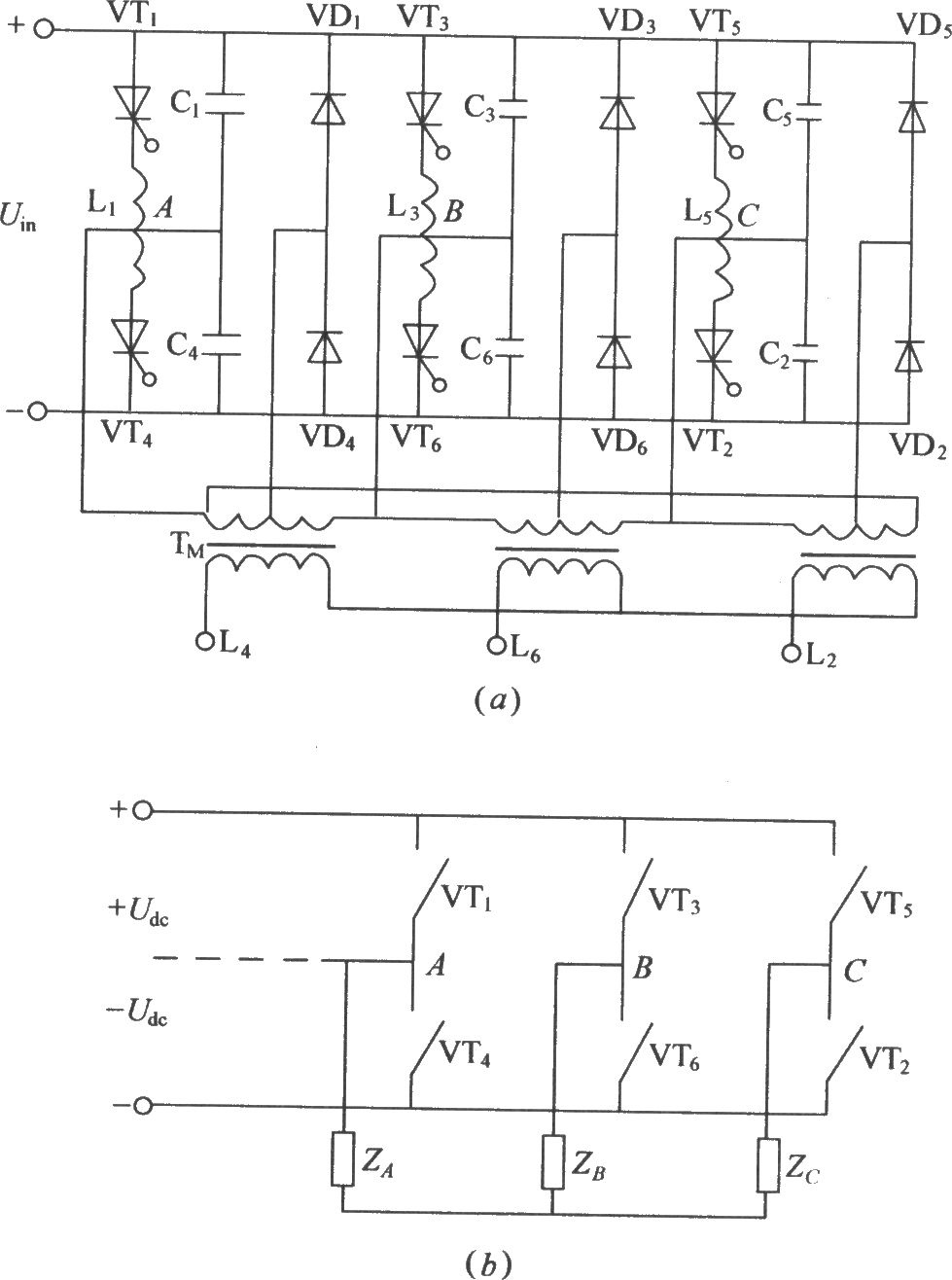
Three phase bridge type inverter circuit diagram
The figure illustrates a traditional three-phase bridge inverter circuit. Components VT1 to VT6 represent thyristors, while L1 to L6 are commutation reactors. Capacitors C1 to C6 serve as commutating capacitors, and the thyristor shut-off circuit is composed of two parts....
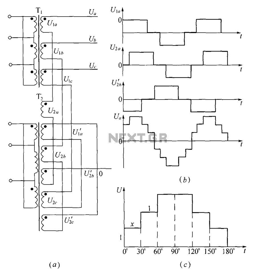
Three-phase step wave inverter output transformer winding connection and the output voltage waveform
As shown, (a) for the three-phase step wave inverter output transformer winding connections; (b) in the figure, its output waveform.
The three-phase step wave inverter is designed to convert direct current (DC) into a three-phase alternating current (AC) output. This inverter...
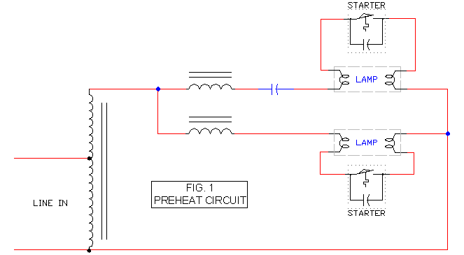
Preheat Ballast Schematic
It includes a starter for each lamp that heats the filaments (cathodes) at both ends of the lamp before ignition. Once the lamp is lit, the heated filaments are no longer necessary. The heating serves solely as an ignition aid....
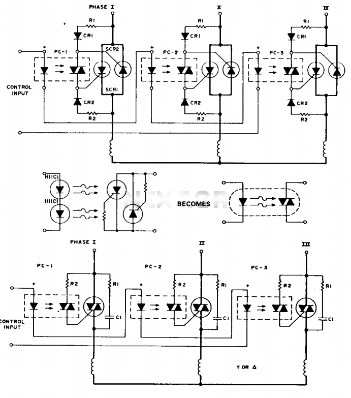
Three-phase switch
To simplify the following schematics and facilitate easy understanding of the principles involved, the following schematic substitution is used. Note that the triac driver is of limited use at 3-phase voltage levels. The following are three-phase switches for low voltage....