


Single-phase motor energy consumption of the two brake circuits
#single-phase motor
#energy consumption
#contactor
#diode rectifier
#AC power supply
#brake circuits
#motor primary
#motor secondary
#220V
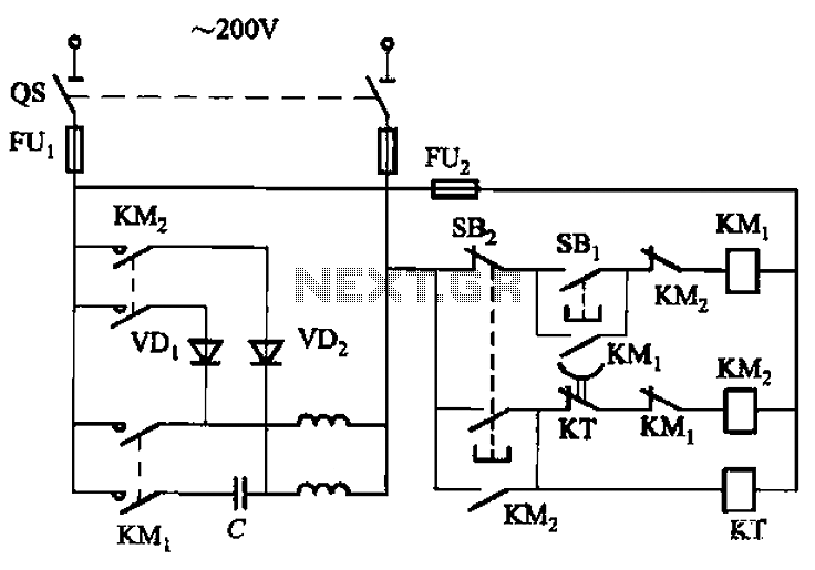
Description: The circuit depicted in Figure 3-150 involves a contactor (KM1) that releases when the system is shut down. The contactor KM2 is energized, allowing a 220V AC power supply to flow through diodes VD1 and VD2, which serve as rectifiers. This configuration applies DC current to the motor's primary and secondary windings, effectively engaging the motor's braking mechanism. After a predetermined delay of 0.2 seconds (adjustable), the time relay (KT) deactivates, concluding the braking process.
The described circuit utilizes a contactor system to manage the operation of an electric motor during shutdown scenarios. The initial release of contactor KM1 signifies that the system is no longer operational. However, contactor KM2 remains engaged to facilitate the application of a 220V AC power supply. The path through diodes VD1 and VD2 is critical, as these components convert the AC voltage to DC, allowing for effective braking by applying the appropriate current to the motor windings.
The braking process is a crucial safety feature that prevents the motor from coasting to a stop, which could lead to mechanical wear or operational hazards. The use of a time relay (KT) introduces an adjustable delay, allowing for fine-tuning of the braking duration based on the specific requirements of the application. This flexibility ensures that the braking action can be adapted to different load conditions or operational scenarios.
In summary, the circuit's design integrates contactors, diodes, and a time relay to create a reliable braking mechanism for electric motors, enhancing both performance and safety during shutdown procedures. The careful selection of components and their arrangement in the circuit is essential for achieving the desired braking characteristics and operational reliability. Circuit shown in Figure 3-150. When shut down, the contactor KM1 released. KMz pull, 220V AC power supply through the diode VDi, VD2 rectifier, the motor primary and secondary windings with DC current braking, the electric motor into the brake status. After a delay (0. 2-ls, adjustable), time relay KT releases, ending the braking process.
The described circuit utilizes a contactor system to manage the operation of an electric motor during shutdown scenarios. The initial release of contactor KM1 signifies that the system is no longer operational. However, contactor KM2 remains engaged to facilitate the application of a 220V AC power supply. The path through diodes VD1 and VD2 is critical, as these components convert the AC voltage to DC, allowing for effective braking by applying the appropriate current to the motor windings.
The braking process is a crucial safety feature that prevents the motor from coasting to a stop, which could lead to mechanical wear or operational hazards. The use of a time relay (KT) introduces an adjustable delay, allowing for fine-tuning of the braking duration based on the specific requirements of the application. This flexibility ensures that the braking action can be adapted to different load conditions or operational scenarios.
In summary, the circuit's design integrates contactors, diodes, and a time relay to create a reliable braking mechanism for electric motors, enhancing both performance and safety during shutdown procedures. The careful selection of components and their arrangement in the circuit is essential for achieving the desired braking characteristics and operational reliability. Circuit shown in Figure 3-150. When shut down, the contactor KM1 released. KMz pull, 220V AC power supply through the diode VDi, VD2 rectifier, the motor primary and secondary windings with DC current braking, the electric motor into the brake status. After a delay (0. 2-ls, adjustable), time relay KT releases, ending the braking process.
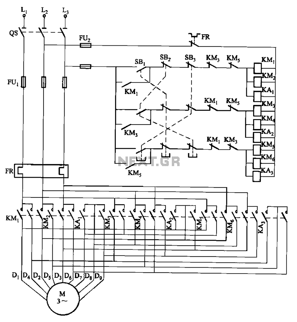
2Y-2Y-2Y-connected three-speed motor contactor control circuit
The circuit depicted in Figure 3-115 utilizes contactors and double buttons, allowing for speed conversion without the need to press the stop button. The buttons SBi, SBz, and SB3 correspond to high, medium, and low-speed operation, respectively.
This circuit design incorporates...

Modified 220V Dimmer Circuit
Note: Do not build or use this if you do not have any knowledge in electrical or electronics. This project is not safe for beginners, and the voltage involved is dangerous and can cause electrocution. Do not exceed the load...
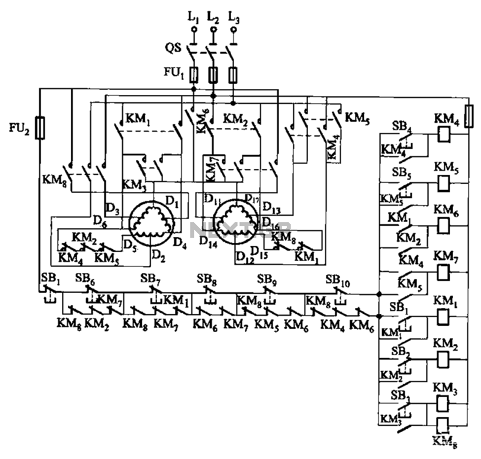
2Y-Y-2 - connection four-speed motor contactor control circuit
The circuit depicted in Figure 3-120 allows for the control of a motor with a capacity of less than the rated current of 5A by using an intermediate relay instead of a contactor. This circuit enables four forward running speeds...
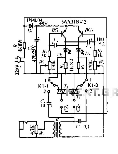
A simple control circuit Lantern
A 220V mains power supply is reduced using a control circuit designed by N. Guanidine D. Yi. The circuit features a spike Bode and provides a +9V voltage supply. It includes components such as a control port (G), a transistor...
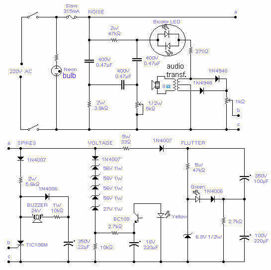
220V Mains Quality Monitor
With this circuit you will be able to monitor the quality of the mains. There are 4 distinct sections, each supervising a parameter pertinent to the quality of the supply line. The noise section consists of a 50Hz filter and...
A simple control circuit Lantern
A 220V mains power supply is reduced using a control circuit designed by N. Guanidine D. Yi. The circuit features a spike Bode and provides a +9V voltage supply. It includes components such as a control port (G), a transistor...
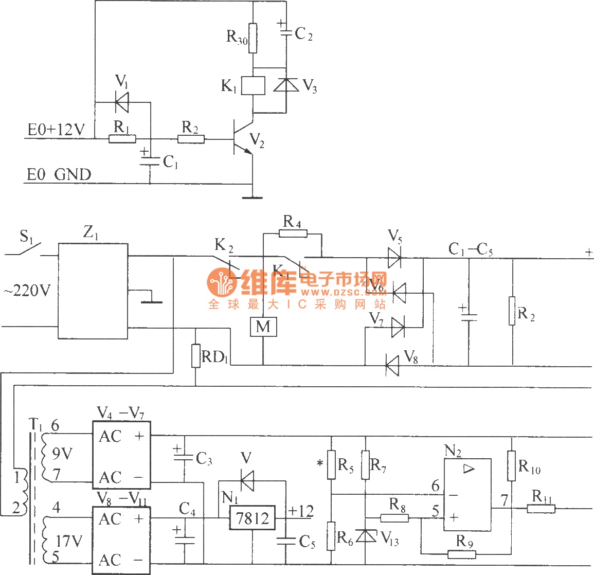
DZW75-48/5050II input circuit
220V (5Hz) alternating voltage passes through the Z1 circuit filter, which filters the signal before sending it to the connection point of the AC over-voltage and under-voltage protection relay K2. During normal operation, the K2 connection point should be closed,...
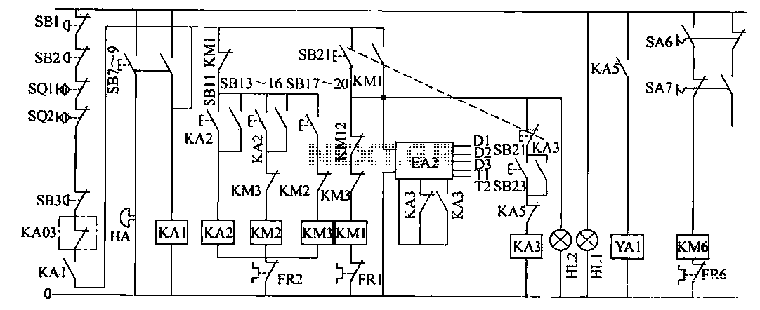
Color offset printing circuit
The operation control circuit is primarily managed by the button switch SB21. The contactor KM1, composed of the main contactor KM1, directly controls the operation of the main motor M1. The main motor M1 serves as the prime mover, while...
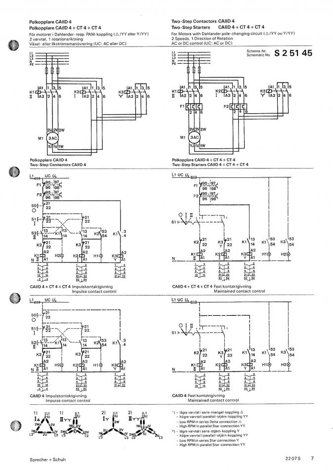
220/440V nameplate on 2-speed motor
A NOS lathe is available, but it lacks any historical information. It appears to be purpose-built, and it is important to note that there is no available technical support for this equipment.
The absence of historical context for the NOS lathe...