


Step-down autotransformer rotor excitation frequency starting circuit
#step-down transformer
#autotransformer
#rotor excitation
#frequency starting
#motor speed control
#delay circuit
#ZQB transformer
#starting circuit
#industrial motor
#electrical engineering
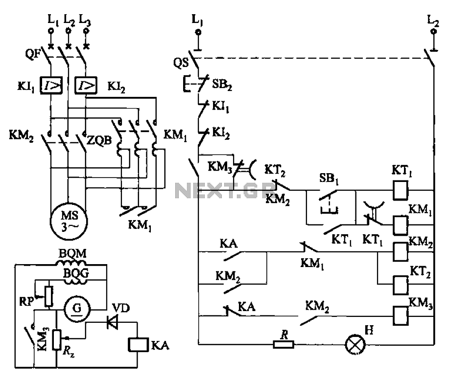
Description: The circuit depicted in Figure 3-187 illustrates the operation of an auto step-down transformer (ZQB). Upon activation, the ZQB transformer initiates a sequence that allows the motor to gradually increase its speed. After a predetermined delay, the ZQB ceases operation, enabling the motor to operate at full pressure. As the motor speed exceeds the quasi-synchronous speed, a short circuit occurs, connecting discharge resistors R to the DC excitation in the rotor winding, which facilitates the synchronous operation of the motor and concludes the startup process.
The circuit operates through a series of controlled steps that ensure smooth acceleration of the motor while maintaining system stability. Initially, the auto step-down transformer (ZQB) reduces the voltage supplied to the motor, allowing it to start under low load conditions. This gradual increase in voltage prevents sudden surges that could damage the motor or associated components.
As the motor reaches a certain speed, defined as the quasi-synchronous speed, the circuit activates a resection mechanism. This mechanism involves the shorting of discharge resistors (R), which are connected to the rotor winding. The purpose of these resistors is to dissipate energy and stabilize the rotor's magnetic field during the transition to synchronous operation. By connecting the DC excitation to the rotor winding at this point, the system ensures that the rotor aligns with the rotating magnetic field produced by the stator, achieving synchronous operation.
The transition from starting to synchronous operation is critical for the efficiency and longevity of the motor. The design of the circuit allows for precise control over the timing of these operations, ensuring that the motor operates within safe parameters while maximizing performance. The inclusion of feedback mechanisms may also be considered to monitor the motor's speed and adjust the excitation levels dynamically, further enhancing operational reliability.
Overall, this circuit design exemplifies a robust approach to motor control, balancing the need for an effective startup sequence with the requirements for operational efficiency in synchronous applications. Circuit shown in Figure 3-187. When you start, then people start auto ZQB step-down transformer. After a period of delay, ZQB out of operation, the motor increases the speed at full pressure. When the speed rises above and quasi-synchronous speed, resection (short) discharge resistors R :, join DC excitation in the rotor winding, synchronous motor synchronous operation was led people to end the startup process.
The circuit operates through a series of controlled steps that ensure smooth acceleration of the motor while maintaining system stability. Initially, the auto step-down transformer (ZQB) reduces the voltage supplied to the motor, allowing it to start under low load conditions. This gradual increase in voltage prevents sudden surges that could damage the motor or associated components.
As the motor reaches a certain speed, defined as the quasi-synchronous speed, the circuit activates a resection mechanism. This mechanism involves the shorting of discharge resistors (R), which are connected to the rotor winding. The purpose of these resistors is to dissipate energy and stabilize the rotor's magnetic field during the transition to synchronous operation. By connecting the DC excitation to the rotor winding at this point, the system ensures that the rotor aligns with the rotating magnetic field produced by the stator, achieving synchronous operation.
The transition from starting to synchronous operation is critical for the efficiency and longevity of the motor. The design of the circuit allows for precise control over the timing of these operations, ensuring that the motor operates within safe parameters while maximizing performance. The inclusion of feedback mechanisms may also be considered to monitor the motor's speed and adjust the excitation levels dynamically, further enhancing operational reliability.
Overall, this circuit design exemplifies a robust approach to motor control, balancing the need for an effective startup sequence with the requirements for operational efficiency in synchronous applications. Circuit shown in Figure 3-187. When you start, then people start auto ZQB step-down transformer. After a period of delay, ZQB out of operation, the motor increases the speed at full pressure. When the speed rises above and quasi-synchronous speed, resection (short) discharge resistors R :, join DC excitation in the rotor winding, synchronous motor synchronous operation was led people to end the startup process.
Motor speed control
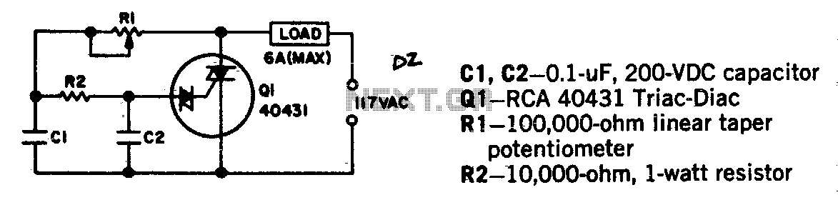
Universal motors and shaded-pole induction motors can be effectively controlled using a full-wave Triac speed controller. Component Q1 integrates both the Triac and diac trigger diodes within a single package. The motor employed for the load should not exceed a...
Motor Speed Control with Battery Eliminator Circuit
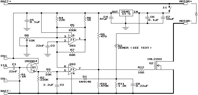
This design is based on one published by Milan Lulic in the German magazine elektroModell. Mr. Lulic's design is for surface mount technology (SMT) construction, whereas mine uses standard off-the-shelf components, and is therefore better suited to construction by the...

Motor speed control
The switching action of the 2N4990 enables the use of smaller capacitors while ensuring reliable triggering of thyristors.
The 2N4990 is a high-speed switching transistor that plays a crucial role in applications requiring efficient control of thyristors. The device's rapid switching...
Conducting pipe control rechargeable delay circuit
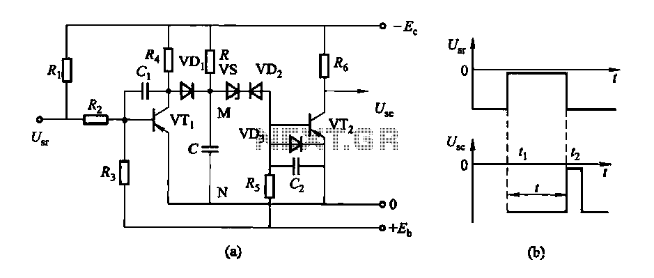
The circuit features a delay action with an instantaneous reset control mechanism. It is categorized into three types: a conducting pipe rechargeable delay circuit, a tube cut-off control rechargeable delay circuit, and a discharge-type delay circuit. In the conducting pipe...
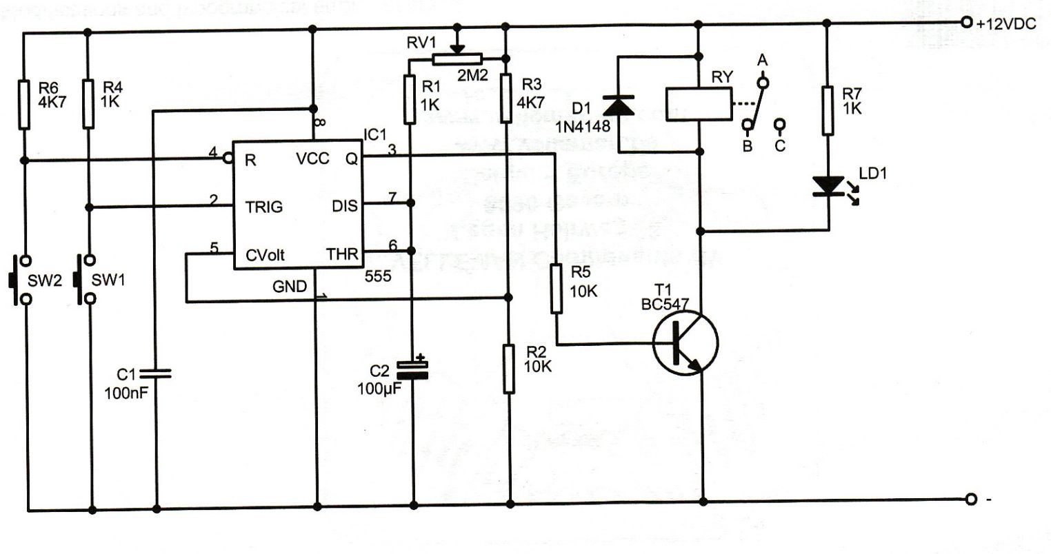
12v 10 minute Off-Delay timer
An Xbox 360 console previously experienced a problem known as the 3 Red Lights of Death (3RLOD). To address this issue, the stock heatsinks were removed, and a Koolance external water cooling system was installed. This modification has effectively resolved...
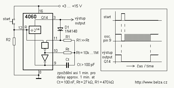
Delay circuit for a long time periods ( 4060 )
If you need a timer circuit, we go after the most proven 555. However, if the delays are longer, based on timing capacitor capacity is too large. In this case, a circuit of Figure 1 After pressing the button -...
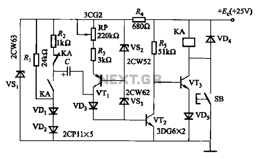
Charging time relay circuit 2
Charging time relay circuit 2 is a long delay circuit. When the capacitor C is 5000 µF, the delay can be up to 1.3 hours. Transistors VT1 and the VS2, VS3 group function as a constant current source to improve...
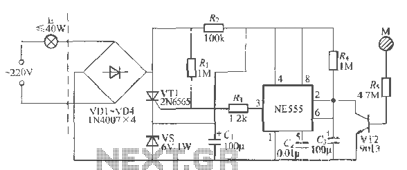
Time base using a delay circuit touch lamp
Using a wire connection, utilize the NFA.55 timebase circuit delay type light touch switch, which can directly replace an ordinary mechanical switch without needing to modify the original internal wiring. The circuit is powered back with good hoof Chapter 96...
simple electronic delay detonator
Here is the circuit for a simple electronic delay detonator circuit diagram. The overall circuit is implemented in a hybrid IC module. The circuit includes a diode bridge connected to the input terminals, a power supply capacitor connected to the...