


Synchronous motor full voltage start-up circuit
#synchronous motor
#voltage start-up
#isolation switch
#vacuum circuit breaker
#circuit breaker coil
#closing coil
#motor protection
#electrical circuit
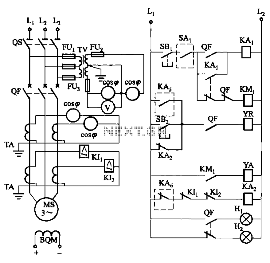
Description: The circuit depicted in Figure 3-186 includes an isolation switch, QF vacuum circuit breakers, YR line for the circuit breaker coil, and YA for the circuit breaker closing coil. Additionally, there is a dashed box representing the excitation device (not shown) that is prepared to activate switches. KAs refers to the excitation device protection relay, which includes contacts for stopping and total loss of voltage protection. SBi is designated as the start button, while SBz is the stop button.
The circuit encompasses various components that are integral to its operation. The isolation switch serves as a critical safety feature, allowing for the disconnection of the circuit from the power source during maintenance or emergencies. The QF vacuum circuit breakers are employed to protect the circuit from overloads and short circuits, ensuring safe operation by interrupting the flow of current when fault conditions arise.
The YR line is responsible for energizing the circuit breaker coil, which is essential for the operation of the circuit breakers. The YA line is connected to the closing coil of the circuit breaker, allowing for the re-engagement of the circuit after a fault has been cleared. The dashed box symbolizes an excitation device that is not explicitly illustrated but plays a vital role in controlling the excitation system of the circuit, ensuring stable operation.
The KAs designation refers to the excitation protection relay, which monitors the excitation levels and provides necessary safeguards against faults. The relay includes contacts that can stop the excitation process and protect against total loss of voltage, which could lead to severe operational issues.
The circuit also incorporates user interface elements, such as the start button (SBi) and stop button (SBz), enabling operators to manually control the circuit's operation. The start button initiates the circuit's function, while the stop button provides a means to safely halt operation when required.
Overall, this circuit is designed for robust operation and safety, integrating advanced protective features and user controls to ensure reliable performance in various operational scenarios. Circuit shown in Figure 3-186. Figure, os for the isolation switch; QF vacuum circuit breakers; YR line for the circuit breaker coil; YA circuit breaker closing coil; SAi dashe d box for excitation device (not shown) ready waiting to run switches; KAs of excitation device excitation protection relay; KAs stop and the total loss of voltage protection relay contacts; SBi as the start button, SBz the stop button.
The circuit encompasses various components that are integral to its operation. The isolation switch serves as a critical safety feature, allowing for the disconnection of the circuit from the power source during maintenance or emergencies. The QF vacuum circuit breakers are employed to protect the circuit from overloads and short circuits, ensuring safe operation by interrupting the flow of current when fault conditions arise.
The YR line is responsible for energizing the circuit breaker coil, which is essential for the operation of the circuit breakers. The YA line is connected to the closing coil of the circuit breaker, allowing for the re-engagement of the circuit after a fault has been cleared. The dashed box symbolizes an excitation device that is not explicitly illustrated but plays a vital role in controlling the excitation system of the circuit, ensuring stable operation.
The KAs designation refers to the excitation protection relay, which monitors the excitation levels and provides necessary safeguards against faults. The relay includes contacts that can stop the excitation process and protect against total loss of voltage, which could lead to severe operational issues.
The circuit also incorporates user interface elements, such as the start button (SBi) and stop button (SBz), enabling operators to manually control the circuit's operation. The start button initiates the circuit's function, while the stop button provides a means to safely halt operation when required.
Overall, this circuit is designed for robust operation and safety, integrating advanced protective features and user controls to ensure reliable performance in various operational scenarios. Circuit shown in Figure 3-186. Figure, os for the isolation switch; QF vacuum circuit breakers; YR line for the circuit breaker coil; YA circuit breaker closing coil; SAi dashe d box for excitation device (not shown) ready waiting to run switches; KAs of excitation device excitation protection relay; KAs stop and the total loss of voltage protection relay contacts; SBi as the start button, SBz the stop button.
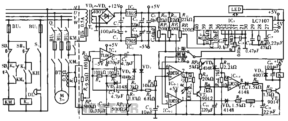
Multifunctional motor protection circuit
The circuit operates during standard inspection work by utilizing the voltage across resistor R2, which is connected to RP, to generate the input signal for IC4. Components R3 through Rg, along with capacitors C7 and C1, and diodes VD7 and...
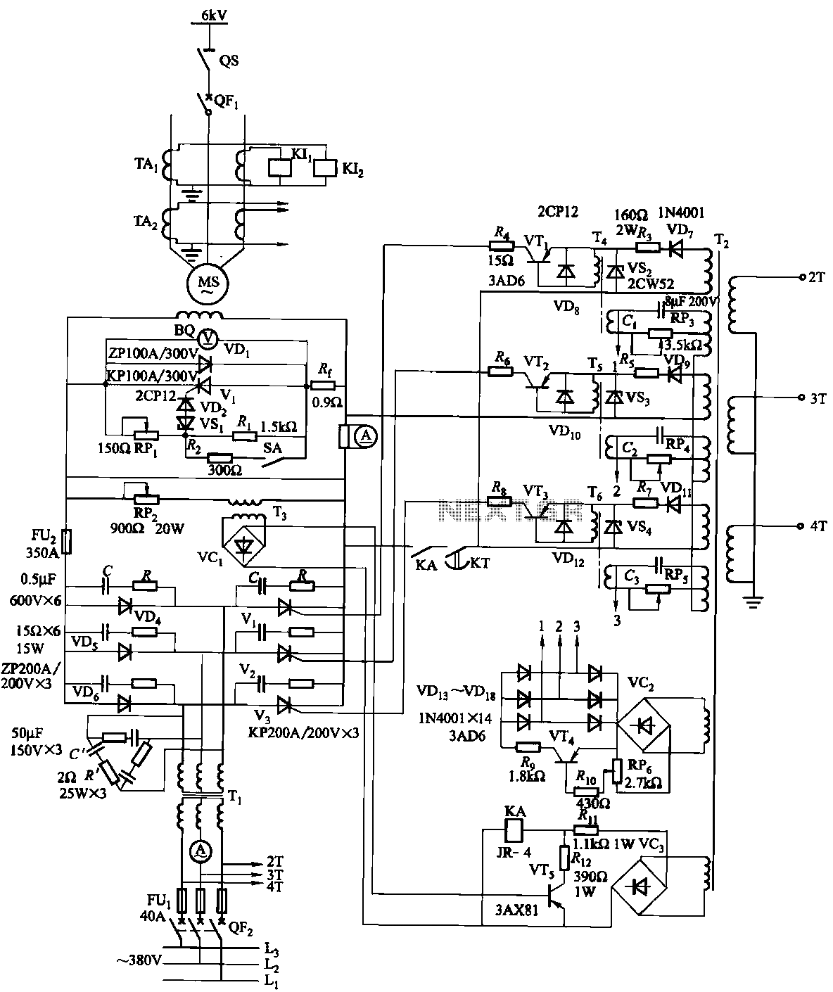
Synchronous motor thyristor excitation circuit
The excitation device for a light-duty synchronous motor rated at 625 kW has been initiated. The triggering circuit of the device consists of three identical RC phase-shift flip-flops. Adjustment potentiometers RP3 to RPs are used to set the RC phase...
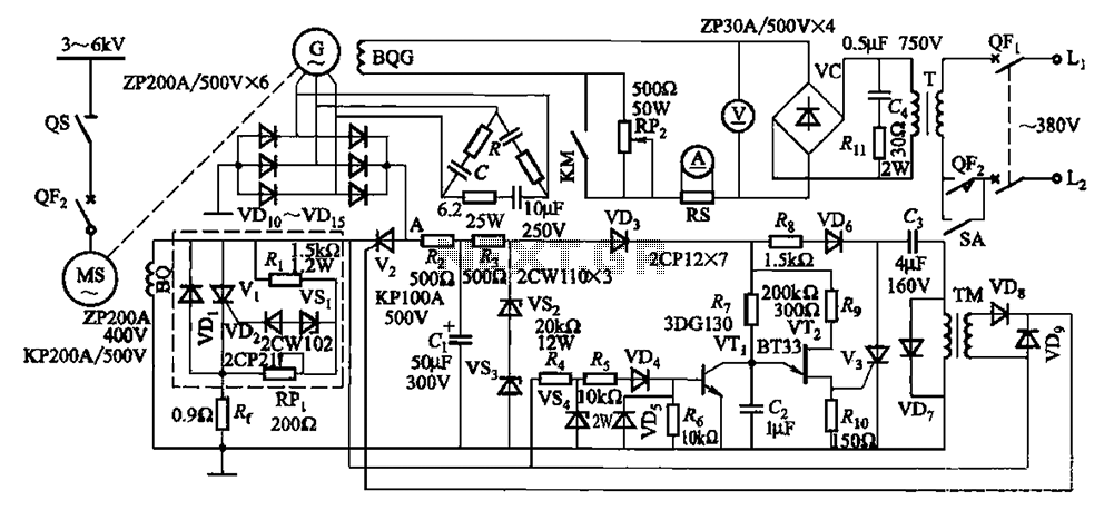
One synchronous motor thyristor excitation circuit
The circuit depicted in Figure 16-105 illustrates a synchronous motor. The components include BQ, which represents its field winding, and G, which denotes the AC excitation for the motor. The notation BQG indicates the field winding, with an empty box...
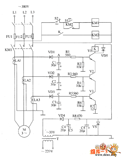
Motor protector circuit diagram 8
The motor protection circuit consists of a power supply circuit, a current detection circuit, and a protection control circuit, as depicted in the accompanying diagram. The power circuit includes a power transformer (T), a rectifier diode (VD4), filter capacitors (C4,...
Synchronous motor thyristor excitation circuit
The excitation device for a light-duty synchronous motor rated at 625 kW has been initiated. The triggering circuit of the device consists of three identical RC phase-shift flip-flops. Adjustment potentiometers RP3 to RPs are used to set the RC phase...
Motor protector circuit diagram 8
The motor protection circuit consists of a power supply circuit, a current detection circuit, and a protection control circuit, as depicted in the accompanying diagram. The power circuit includes a power transformer (T), a rectifier diode (VD4), filter capacitors (C4,...