


Synchronous motor thyristor excitation circuit
#synchronous motor
#thyristor
#excitation circuit
#triggering device
#motor control
#625kW
#light duty
#three-phase
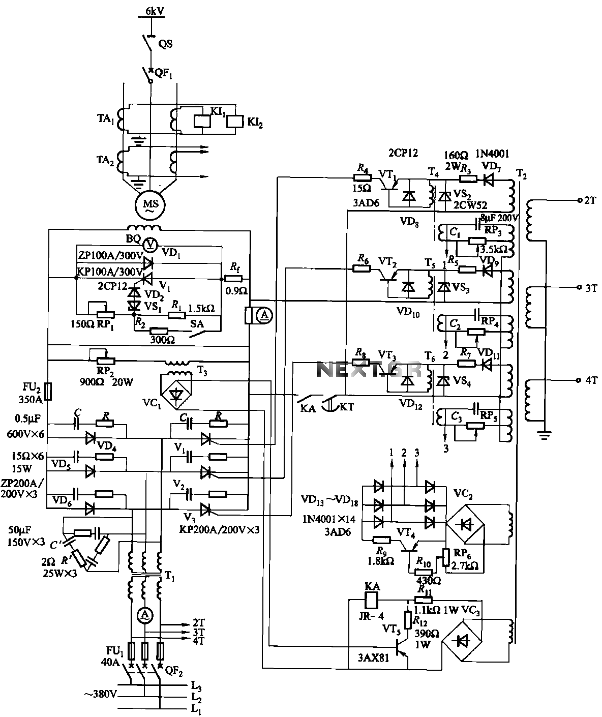
Description: The excitation device for a light-duty synchronous motor rated at 625 kW has been initiated. The triggering circuit of the device consists of three identical RC phase-shift flip-flops. Adjustment potentiometers RP3 to RPs are used to set the RC phase shift bridge phase between 0 and 150 degrees, allowing for control over the rotor excitation current magnitude.
The excitation device is critical for the operation of synchronous motors, which require precise control of rotor excitation to maintain synchronism with the stator's rotating magnetic field. The use of three identical RC phase-shift flip-flops in the triggering circuit provides a robust method for generating the necessary phase shifts. Each flip-flop can be configured to introduce a specific delay, effectively creating a phase shift that can be finely tuned using the adjustment potentiometers.
The adjustment potentiometers RP3 to RPs play a vital role in calibrating the phase shift within the circuit. By varying the resistance in the RC network, the phase angle can be set between 0 and 150 degrees. This flexibility allows for precise control of the excitation current supplied to the rotor, which is essential for optimizing the performance of the synchronous motor under varying load conditions.
The design of the excitation circuit must ensure stability and reliability. The RC phase-shift network must be designed to minimize noise and interference, which can adversely affect the operation of the synchronous motor. Additionally, the choice of components for the flip-flops and the potentiometers should be made with consideration for their thermal characteristics and voltage ratings to ensure long-term operation without failure.
Overall, the described excitation device is a sophisticated control system that allows for enhanced performance and efficiency of light-duty synchronous motors, making it suitable for various industrial applications where precise motor control is required.The excitation device for light duty synchronous motor 625kW initiated. Triggering the device circuit consists of three identical RC phase-shift flip-flops. Adjustment potentiometer RP3 ~ RPs, make RC phase shift bridge phase O. ~ 150. Changes to control the size of the rotor excitation current.
The excitation device is critical for the operation of synchronous motors, which require precise control of rotor excitation to maintain synchronism with the stator's rotating magnetic field. The use of three identical RC phase-shift flip-flops in the triggering circuit provides a robust method for generating the necessary phase shifts. Each flip-flop can be configured to introduce a specific delay, effectively creating a phase shift that can be finely tuned using the adjustment potentiometers.
The adjustment potentiometers RP3 to RPs play a vital role in calibrating the phase shift within the circuit. By varying the resistance in the RC network, the phase angle can be set between 0 and 150 degrees. This flexibility allows for precise control of the excitation current supplied to the rotor, which is essential for optimizing the performance of the synchronous motor under varying load conditions.
The design of the excitation circuit must ensure stability and reliability. The RC phase-shift network must be designed to minimize noise and interference, which can adversely affect the operation of the synchronous motor. Additionally, the choice of components for the flip-flops and the potentiometers should be made with consideration for their thermal characteristics and voltage ratings to ensure long-term operation without failure.
Overall, the described excitation device is a sophisticated control system that allows for enhanced performance and efficiency of light-duty synchronous motors, making it suitable for various industrial applications where precise motor control is required.The excitation device for light duty synchronous motor 625kW initiated. Triggering the device circuit consists of three identical RC phase-shift flip-flops. Adjustment potentiometer RP3 ~ RPs, make RC phase shift bridge phase O. ~ 150. Changes to control the size of the rotor excitation current.
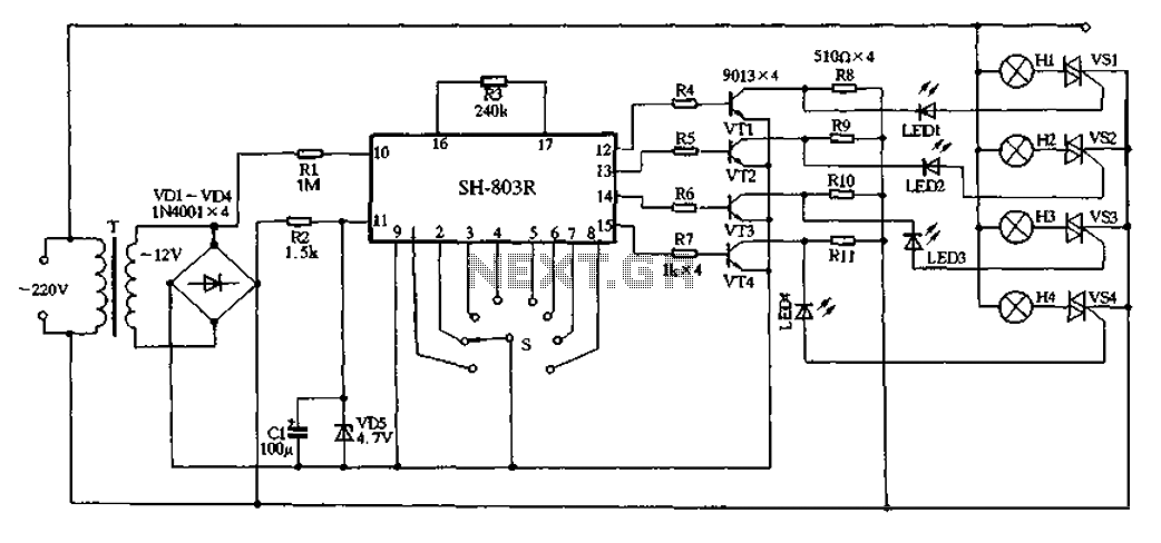
SH-803R produced by high-power holiday lights
22V AC is supplied through thyristors VSl to VS4 for lighting control. The current is routed through transformer T, followed by rectification using diodes VD1 to VD4, and regulated by VD5 to provide a filtered output of approximately 4.7V DC....
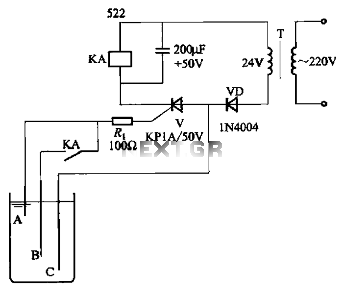
Level one thyristor-controlled circuit sink type b
The circuit depicted in Figure 11-14 utilizes a unidirectional thyristor within liquid level automatic control systems. It incorporates electrodes that serve as sensing elements for detecting the level of water or other conductive liquids. The circuit features a current limiting...
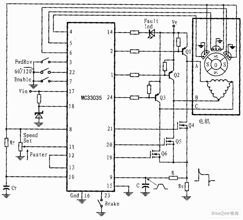
Three-phase and Six-step Motor Control Circuit of MC33035
The presented three-phase application circuit features a motor controller circuit connection diagram that operates using a full-wave six-step method. The power switch is a Darlington PNP type, while the lower power switch is an N-channel power MOSFET. Each device incorporates...
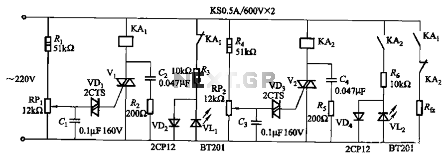
Mains undervoltage overvoltage protection circuit of five
Bidirectional thyristor control. By adjusting potentiometers RPi and RPz, the lower and upper limit values can be changed. LEDs VLi and VL2 serve as indicators for low pressure and high pressure, respectively.
The circuit utilizes a bidirectional thyristor to control the...
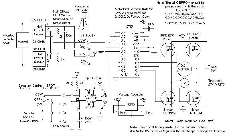
Motorized Video Camera Mount
The camera rotator circuit utilizes a 2716 EPROM to store a logic value table that governs the motor driver (H-bridge) circuit. The schematic illustrates the EPROM data. By employing the EPROM, a significant number of discrete gates are eliminated. The...
Three-phase and Six-step Motor Control Circuit of MC33035
The presented three-phase application circuit features a motor controller circuit connection diagram that operates using a full-wave six-step method. The power switch is a Darlington PNP type, while the lower power switch is an N-channel power MOSFET. Each device incorporates...
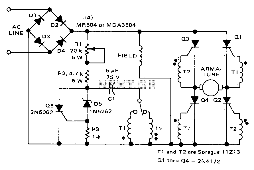
Direction and speed control
This circuit functions similarly to the one depicted in Fig. 57-4. The key differences include the placement of the field across the rectified supply and the armature being positioned within the SCR bridge. Therefore, the field current is unidirectional while...
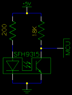
Gray Projects
After learning to operate the device, it became evident that inertia posed a significant challenge. The constructed system is notably heavy, making it difficult to initiate motor operation at full speed. Despite having some understanding of physics, practical experience is...
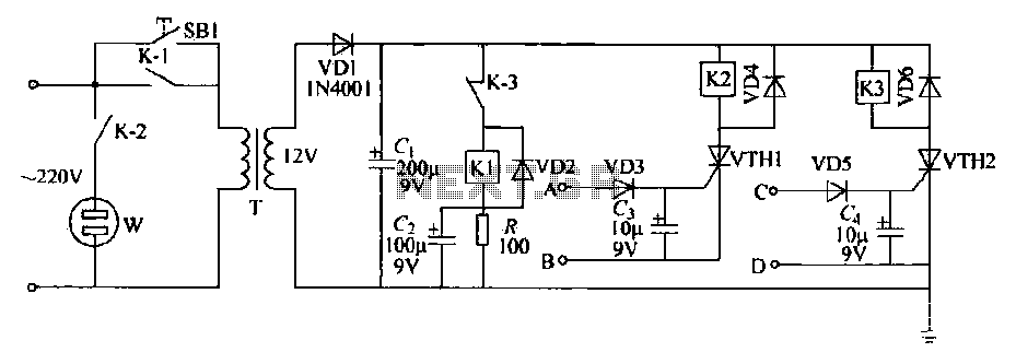
Dual timing circuit thyristor control table
This schematic circuit features two alarm outputs controlled by a timer using thyristors. The system can be turned on or off and will shut down after the power supply is interrupted. It employs a transformer on the primary side for...