


Three-phase and Six-step Motor Control Circuit of MC33035
#three-phase
#six-step
#MC33035
#Darlington PNP
#power MOSFET
#motor controller
#full wave
#stator inductance
#power supply
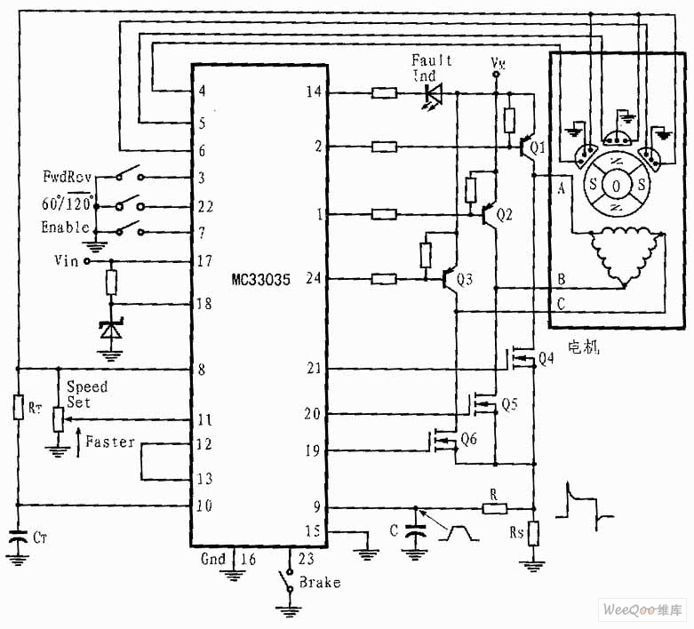
Description: The presented three-phase application circuit features a motor controller circuit connection diagram that operates using a full-wave six-step method. The power switch is a Darlington PNP type, while the lower power switch is an N-channel power MOSFET. Each device incorporates a parasitic catching diode, allowing stator inductance energy to return to the power supply.
The three-phase motor controller circuit is designed to drive a three-phase induction motor efficiently. The full-wave six-step control method enhances the performance by providing a smoother operation compared to traditional methods. The use of a Darlington PNP transistor for the power switch allows for higher current gain and reduced base current requirements, making it suitable for applications where efficiency is critical.
The N-channel power MOSFET serves as the lower switch due to its lower on-resistance and faster switching capabilities, which contribute to improved thermal performance and efficiency. The integration of parasitic catching diodes in both the Darlington and MOSFET ensures that any back EMF generated by the motor during operation is safely redirected back to the power supply, preventing damage to the circuit components.
The circuit typically includes additional components such as gate resistors, snubber circuits, and possibly a microcontroller for PWM (Pulse Width Modulation) control, which allows for precise speed and torque control of the motor. The PWM technique modulates the voltage and current supplied to the motor, optimizing performance based on load conditions.
Overall, this three-phase motor controller circuit is an effective solution for driving three-phase motors in various industrial and automation applications, providing reliability and efficiency in performance.The shown three-phase application circuit owns motor controller circuit connection diagram which is driven by full wave six-step.The power switch triode is Darlington PNP type and the lower power switch triode is N groove power MOSFET. Each device contains a parasitic catching diode thus it can make stator inductance energy return power supply.The output c..
The three-phase motor controller circuit is designed to drive a three-phase induction motor efficiently. The full-wave six-step control method enhances the performance by providing a smoother operation compared to traditional methods. The use of a Darlington PNP transistor for the power switch allows for higher current gain and reduced base current requirements, making it suitable for applications where efficiency is critical.
The N-channel power MOSFET serves as the lower switch due to its lower on-resistance and faster switching capabilities, which contribute to improved thermal performance and efficiency. The integration of parasitic catching diodes in both the Darlington and MOSFET ensures that any back EMF generated by the motor during operation is safely redirected back to the power supply, preventing damage to the circuit components.
The circuit typically includes additional components such as gate resistors, snubber circuits, and possibly a microcontroller for PWM (Pulse Width Modulation) control, which allows for precise speed and torque control of the motor. The PWM technique modulates the voltage and current supplied to the motor, optimizing performance based on load conditions.
Overall, this three-phase motor controller circuit is an effective solution for driving three-phase motors in various industrial and automation applications, providing reliability and efficiency in performance.The shown three-phase application circuit owns motor controller circuit connection diagram which is driven by full wave six-step.The power switch triode is Darlington PNP type and the lower power switch triode is N groove power MOSFET. Each device contains a parasitic catching diode thus it can make stator inductance energy return power supply.The output c..
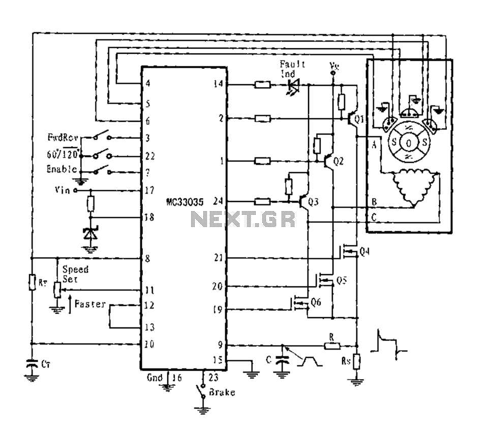
Three-phase six-step motor control circuit diagram composed of MC33035
The application circuit is a three-phase full-wave six-step driving circuit for an open-loop motor controller. It features a power switching transistor of the Darlington type, specifically PNP, while the lower power switching transistors are N-channel power MOSFETs. Each device incorporates...
2 watt switching power supply
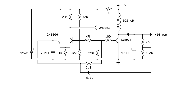
This compact switching power supply utilizes a Schmitt trigger oscillator to control a switching transistor, which provides current to a small inductor. When the transistor is activated, energy accumulates in the inductor, and this energy is subsequently released into the...
Soft Start For Switching Power Supply
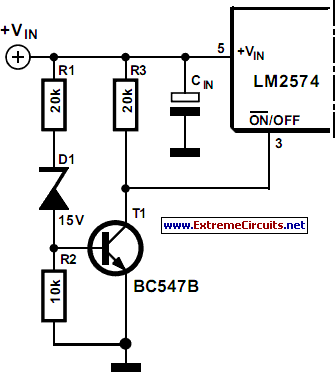
A switching power supply that has an output voltage significantly lower than its input voltage exhibits a unique characteristic: the current drawn from the supply is less than the output current. However, the input power (UI) is, naturally, greater than...
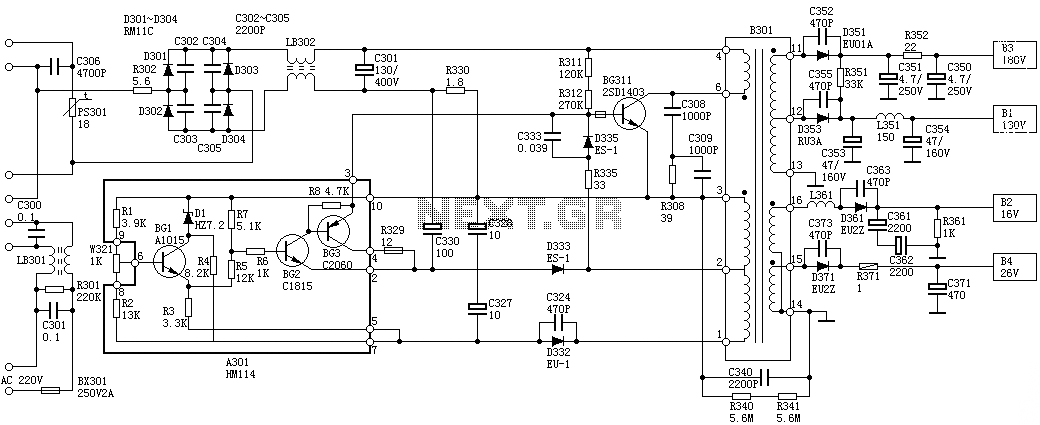
Sanyo 83P switching power supply circuit diagram
Oscillation: The positive terminal voltage of C310 is approximately 300V. The resistors R311 and R312 are connected to the switch BG311 at the B pole, while the B301 winding via the switching transformer (4) and (6) is connected to the...
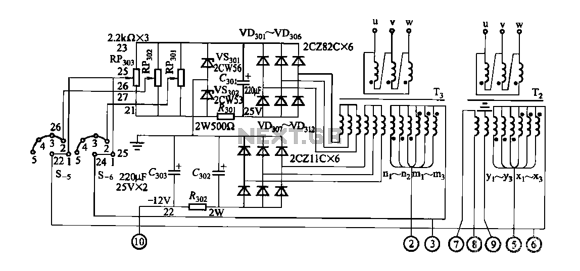
FGDF-3 three-phase low-temperature iron plating power supply circuit
FGDF-3 is a three-phase low-temperature iron plating power supply circuit, while the KGDF-3 is a single-phase low-temperature iron plating power supply device that encompasses all the characteristics of the power supply unit. This design allows for an even distribution of...
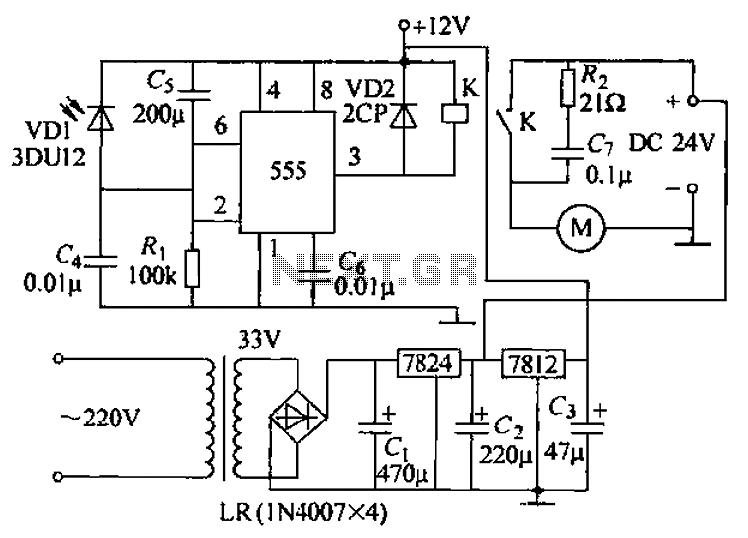
Remote tracking circuit schematics
The circuit consists of two main components: (1) a power supply circuit featuring a transformer (T) that steps down AC 220V to 33V, followed by a full-wave rectifier, a filter, and a three-terminal regulator that outputs +24V. This circuit also...
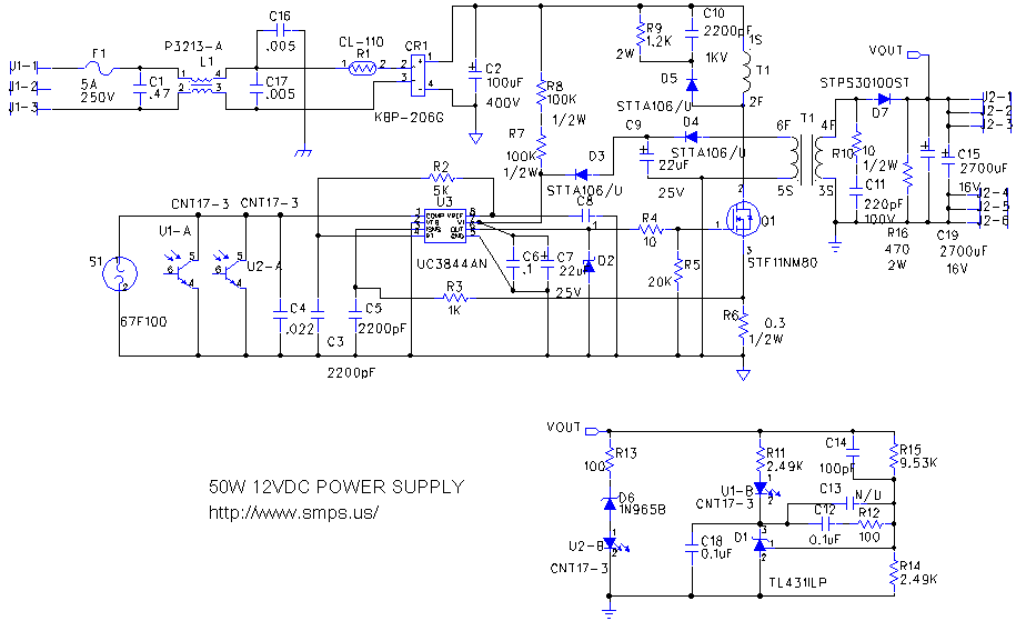
switching power supply 2
This circuit is designed to double nearly any DC input voltage while handling a substantial amount of current. For instance, it can work with input voltages ranging from 12 to 24V. With minor modifications, it can also provide any desired...
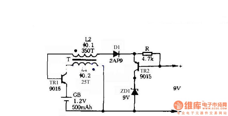
Self-control digital inverter power supply circuit diagram:1.2V rising to 9V
The circuit does not require a separate power switch or transformation to control the switches on the table. It offers advantages such as low power consumption, stability, reliability, and no impact on instrument accuracy. The transformer T in the circuit...
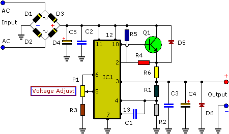
3-30V 3A Adjustable Regulated DC Power Supply
This power supply is designed as either an auxiliary or a permanent power source for various circuits that require a stabilized DC voltage ranging from 3 to 30V, with a maximum current consumption of 3A. Additionally, this power supply unit...