


transistors Can someone help me understand this H-Bridge
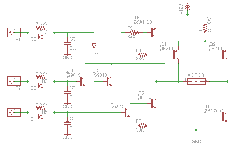
Description: An old RC car is available, but it lacks the transmitter. A custom receiver/transmitter has been built using a microcontroller and a 2.4 GHz transceiver. However, there is uncertainty regarding the functionality of the car's original H-Bridge circuit.
The H-Bridge is a crucial component in controlling the direction and speed of a DC motor, which is typically used in RC cars for propulsion. It allows the voltage to be applied across the motor terminals in either direction, enabling forward and reverse motion. Understanding the operation of the H-Bridge is essential for integrating it with the custom-built receiver and transmitter.
An H-Bridge typically consists of four switches (transistors or MOSFETs) arranged in a configuration that can control the voltage across the motor. The basic operation involves the following states:
1. **Forward Motion**: To drive the motor forward, switches Q1 and Q4 are turned on, while Q2 and Q3 remain off. This configuration allows current to flow through the motor in one direction.
2. **Reverse Motion**: To reverse the motor's direction, switches Q2 and Q3 are activated, while Q1 and Q4 are turned off. This change in switch states reverses the current flow through the motor.
3. **Braking**: To stop the motor quickly, both pairs of switches (Q1 & Q2 or Q3 & Q4) can be turned on simultaneously, creating a short circuit across the motor terminals.
4. **Coasting**: All switches can be turned off, allowing the motor to coast to a stop with no active braking.
When integrating the H-Bridge with the microcontroller and the 2.4 GHz transceiver, it is important to ensure that the control signals from the microcontroller are compatible with the H-Bridge's input requirements. The microcontroller can be programmed to send PWM signals for speed control and digital signals for direction control based on the commands received from the transceiver.
To implement this, the microcontroller's GPIO pins can be connected to the control inputs of the H-Bridge. The transceiver will receive the control commands from the user and transmit them to the microcontroller, which will then interpret these commands and activate the appropriate switches in the H-Bridge.
In summary, understanding the H-Bridge's operation is vital for successful integration with the custom Rx/Tx system. Proper configuration and control of the H-Bridge will enable the RC car to operate as intended, with both forward and reverse motion capabilities, as well as speed control.An old RC car but without the transmitter so I built my own Rx/Tx using MCU and 2. 4Ghz transceiver, however, I want to use the car`s original H-Bridge but not sure if I understood how that circuit works.
The H-Bridge is a crucial component in controlling the direction and speed of a DC motor, which is typically used in RC cars for propulsion. It allows the voltage to be applied across the motor terminals in either direction, enabling forward and reverse motion. Understanding the operation of the H-Bridge is essential for integrating it with the custom-built receiver and transmitter.
An H-Bridge typically consists of four switches (transistors or MOSFETs) arranged in a configuration that can control the voltage across the motor. The basic operation involves the following states:
1. **Forward Motion**: To drive the motor forward, switches Q1 and Q4 are turned on, while Q2 and Q3 remain off. This configuration allows current to flow through the motor in one direction.
2. **Reverse Motion**: To reverse the motor's direction, switches Q2 and Q3 are activated, while Q1 and Q4 are turned off. This change in switch states reverses the current flow through the motor.
3. **Braking**: To stop the motor quickly, both pairs of switches (Q1 & Q2 or Q3 & Q4) can be turned on simultaneously, creating a short circuit across the motor terminals.
4. **Coasting**: All switches can be turned off, allowing the motor to coast to a stop with no active braking.
When integrating the H-Bridge with the microcontroller and the 2.4 GHz transceiver, it is important to ensure that the control signals from the microcontroller are compatible with the H-Bridge's input requirements. The microcontroller can be programmed to send PWM signals for speed control and digital signals for direction control based on the commands received from the transceiver.
To implement this, the microcontroller's GPIO pins can be connected to the control inputs of the H-Bridge. The transceiver will receive the control commands from the user and transmit them to the microcontroller, which will then interpret these commands and activate the appropriate switches in the H-Bridge.
In summary, understanding the H-Bridge's operation is vital for successful integration with the custom Rx/Tx system. Proper configuration and control of the H-Bridge will enable the RC car to operate as intended, with both forward and reverse motion capabilities, as well as speed control.An old RC car but without the transmitter so I built my own Rx/Tx using MCU and 2. 4Ghz transceiver, however, I want to use the car`s original H-Bridge but not sure if I understood how that circuit works.
how to convert a 9v battery to 3.7v
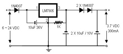
A regulator circuit is needed for this DIY project. Familiarity with electronic components, circuitry, the use of a multitester, and a soldering iron is essential. The schematic diagram provided can accept an input voltage ranging from 6 to 24 volts...
h bridge How can I implement regenerative braking of a DC motor
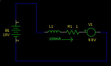
Many electric vehicles can convert the momentum of the car into stored energy in batteries, instead of dissipating it as heat in the brake pads. This process is known as regenerative braking. It can be implemented using a motor controlled...
simplify MCU circuit design
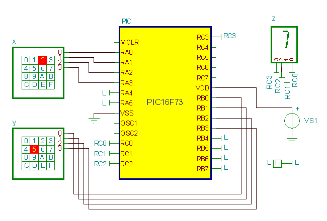
Writing assembly code for microcontrollers (MCUs) can often be a challenging and time-consuming process. However, software development can be streamlined, allowing more time for electronics hardware design by utilizing TINA's Flowchart editor and debugger. This tool enables the generation and...
sn754410
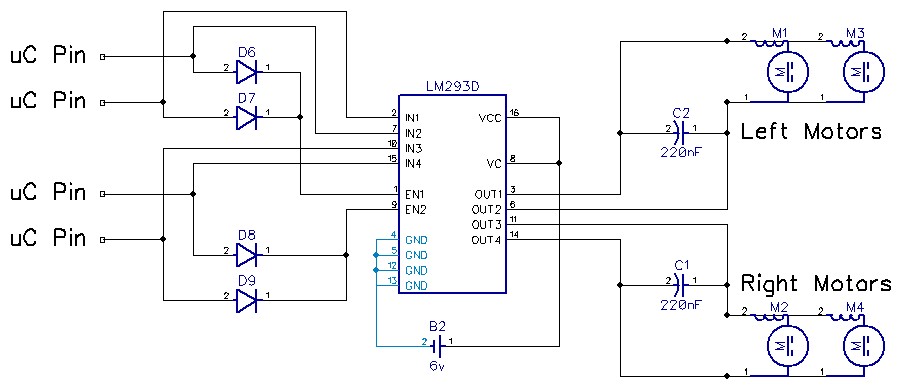
After testing the motors, a current draw of up to 1.3 Amps was observed. Two SN754410 H-Bridges were stacked, and a heat sink was constructed from an aluminum can. This setup should handle 2 Amps or more. The heat sink...
Simple Remote Control Tester
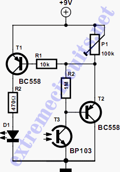
The circuit biases the BC558 transistor, causing LED D1 to flash in response to signals from the remote control. The preset resistor in the circuit sets the sensitivity level.
The circuit utilizes a BC558 PNP transistor, which plays a crucial role...
Wifi Robot
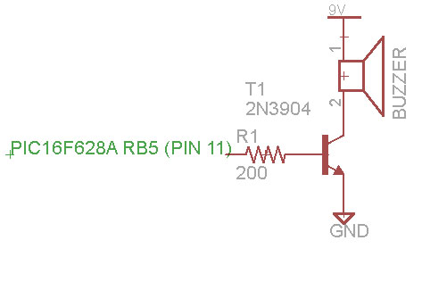
A remote control car can be operated over the internet or wirelessly from a laptop up to 500 meters away. It features a live-feed network camera for driving without line of sight and a horn for signaling. The project utilizes...
Remote Controlled Appliance Switch Circuit
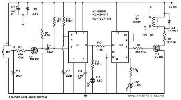
The circuit diagram of a remote-controlled appliance switch circuit includes two main components: IC1 (NE 555) and IC2 (CD 4017).
The remote-controlled appliance switch circuit is designed to allow users to control electrical appliances wirelessly. The heart of this circuit is...
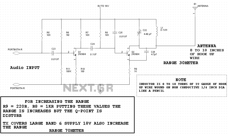
The Autonomous Drifter Circuit
The first schematic examined is the base schematic of the transmitter without any modifications. The RC car's transmitter circuit consists of two halves. One side (on the left) is predominantly digital. When a switch (1-4) is pressed, IC1 becomes active,...
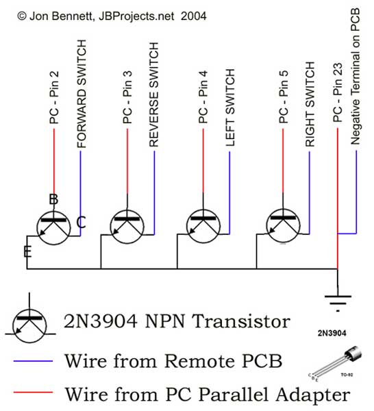
PC Controlled RC Car
This project article was originally written in 2004 when most computers had parallel ports. This is no longer the case, so much of this information is now outdated. The Mini RC Car Project has been one of the most favored...