

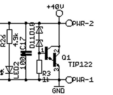

TB6560 Stepper Motor Driver Boards
Attached are 3 captures from my L297/L298 board using the same motor at 500, 750 and 900 steps/sec on a 36v supply, wired bipolar parallel (coil resistance = 3....
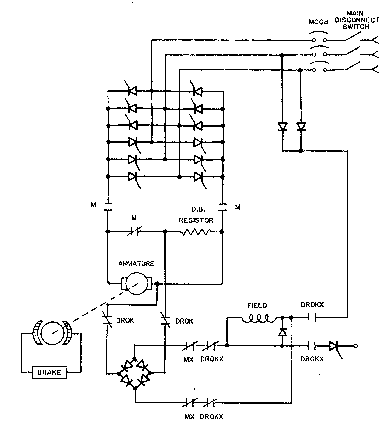
APPLICATION OF DYNAMIC BRAKING TO MINE HOISTING SYSTEMS
...
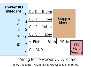
Controlling Stepper Motors Using Power IO Wildcard MOSFET Driver
For maximum efficiency, set MAX_STEPPERS equal to the number of stepper motors that you are controlling (but never more than 4). Motors are referred to by their...
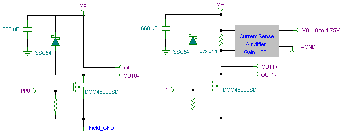
Pulse Width Modulation PWM Controller Board for DC Loads/devices
PWM pulse width modulation controller board allows 9S12/HCS12 microcontroller or PIC microcontrollers to output 8 channels at 5 DC amps each with current sensin...
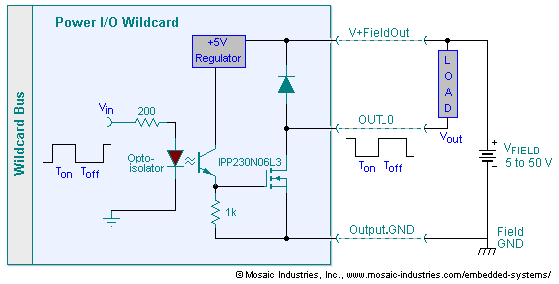
8-Channel High-Current Opto-Isolated Open-drain MOSFET Driver motor Board
Embedded I/O board provides isolated high voltage switch inputs and eight high current high voltage DC outputs using optically isolated, open drain N-MOSFET tra...
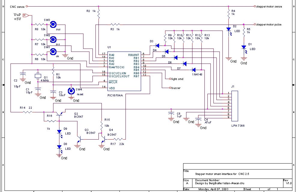
Stepper circuit
...
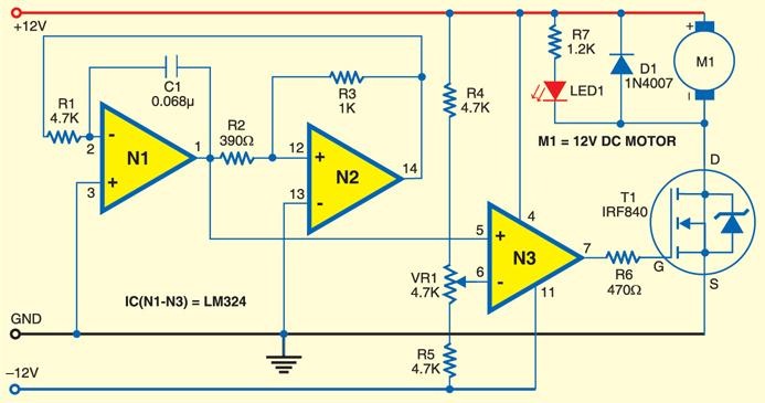
small dc motor control using pwm
...
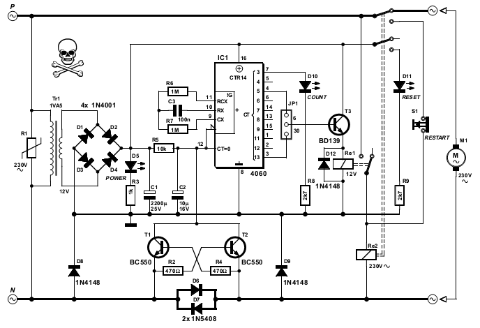
pump protector schematic
...
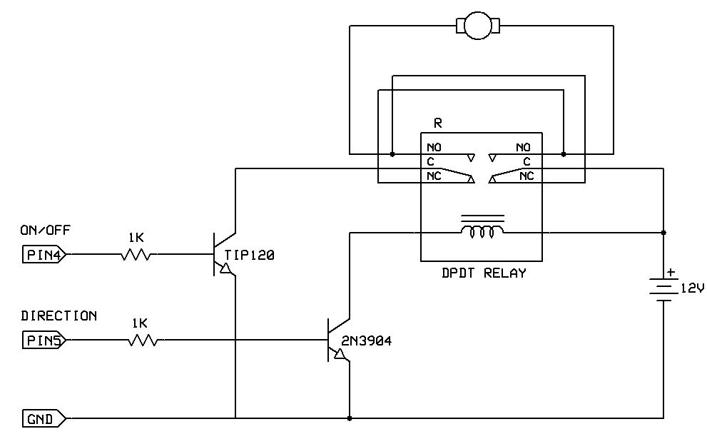
Bidirectional motor control
One of the simplest ways to get a motor to turn in both directions is by using a double-pole, double-throw (DPDT) relay. Along with the relay, this hookup requi...
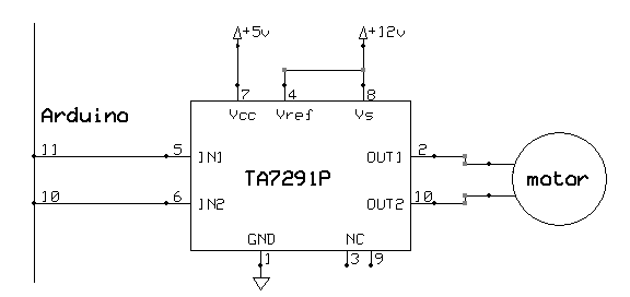
DC Motor Control
We used buffer IC`s (7417, 7414) to isolate the signals to and from the Arduino. This protected the board, and provided power for external devices without drawi...
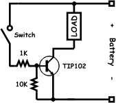
BJT H-bridge Implementation
Because these transistors are a complementary pair, the circuit using them is very symmetrical. The upper right and upper left corners of the H-bridge are calle...
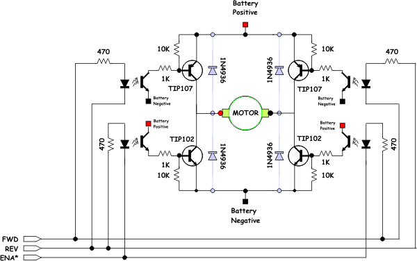
BJT H-bridge Circuit Details
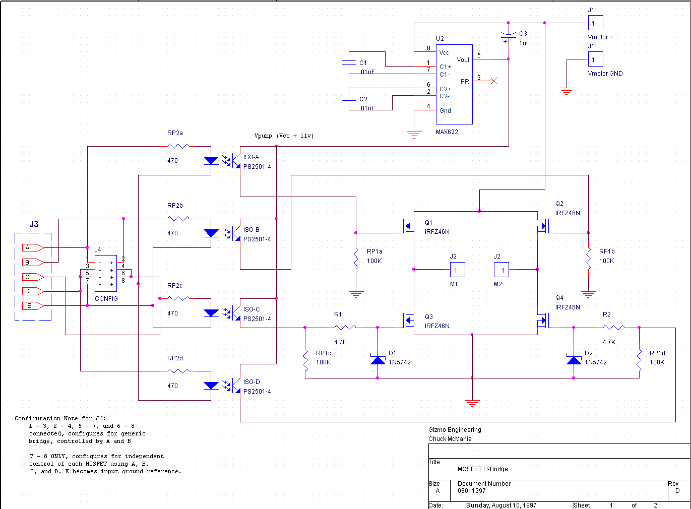
You should notice that the opto-isolator LEDs are connected to three wires labeled "FWD", "REV", and "ENA*. " These wires deserve a bit of explanation. The FWD,...
Assembling The Speed Controller
The. 01uf monolithic capacitors will be marked `103 K` and the 15pf monolithic capacitors are marked `15 J`. It is very important that you don`t confuse the two...

Designing Robust and Fault-Tolerant Motion-Control Feedback Systems
This article reviews basic servo systems and development of the fault-tolerant feedback systems for servo systems. Controller receiver circuit design, proper PC...
L298N Stepper Motor Driver Controller Board for Arduino
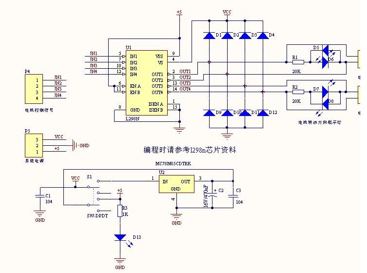
The L298N driver module contains the ST` L298N chip, ususlly used to drive two 3-30V DC motor, there is a 5V output interface, power for 5V single-chip circuitr...
Arduino Running A DC Motor and High Current Lamp
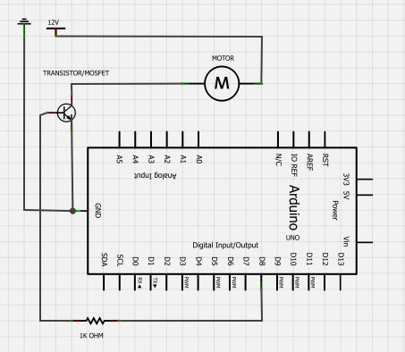
BC547 transistor. Max operating current is 100 mA while max voltage is 65 volts. With the transistorlabelfacing the reader, the three legs from left to right ar...
Stepper Motor Driver
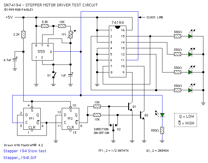
Based on the SN74LS194 - Bidirectional Universal Shift Register the circuit is designed to drive UNIPOLAR type stepper motors and provides only basic control fu...

AC motor control circuits
...
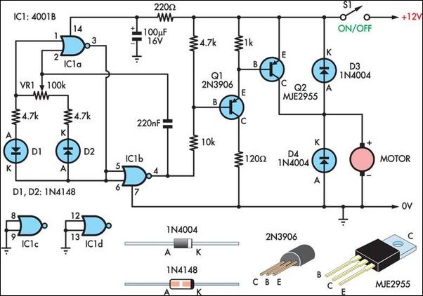
Two Basic Motor Speed Controllers
Here are two simple 12V DC motor speed controllers that can be built for just a few dollars. They exploit the fact that the rotational speed of a DC motor is di...
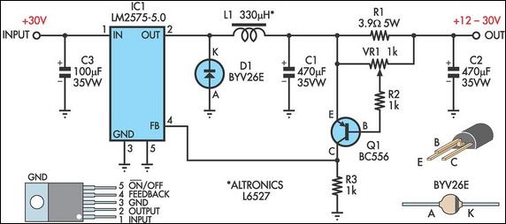
Switchmode Constant Current Source
Operating a stepper motor using a fixed (constant) voltage supply results in poor torque at high speeds. In fact, stepper motors tend to stall at fairly low spe...