


Differential Analog Circuit Switch
#differential multiplexer
#analog switch
#LM107
#RDS (ON)
#common mode signals
#temperature range
#FM1208
#precision circuits
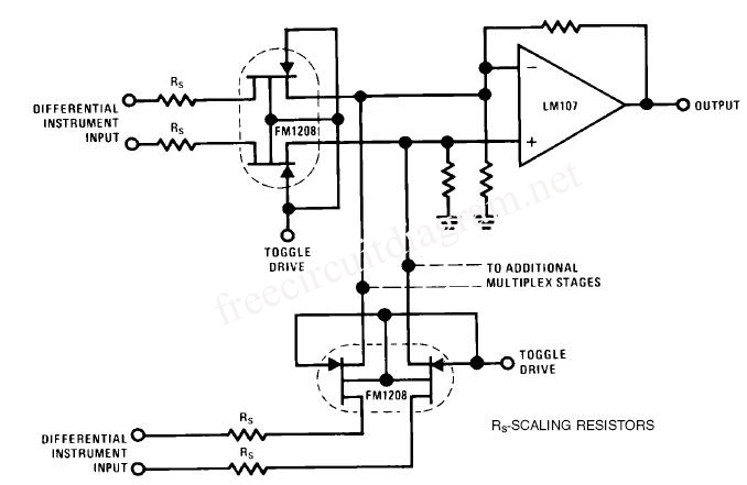
Description: This circuit is a differential analog switch circuit utilizing the FM1208 monolithic dual differential multiplexer. It is designed for applications where the on-resistance (RDS(ON)) must match closely. The RDS(ON) for the monolithic dual multiplexer exhibits better than 1% accuracy across a broad temperature range of -25 to 125 °C, making it an exceptional choice for precise multiplexer applications. This characteristic significantly minimizes close tracking errors caused by common mode signals. The operational amplifiers used in this circuit are LM107.
The circuit features a dual differential multiplexer configuration, which allows for the selection of multiple analog input signals while maintaining signal integrity. The FM1208 multiplexer is specifically designed to minimize the variations in on-resistance, ensuring that the selected signals are accurately represented at the output. This is particularly crucial in applications where precision is paramount, such as in instrumentation and sensor interfacing.
The LM107 operational amplifiers are selected for their low offset voltage and low bias current, which further enhances the accuracy of the circuit. These op-amps are configured in a way that optimizes the performance of the multiplexer, providing high input impedance and low output impedance, which is essential for driving loads without significant signal degradation.
In addition to the multiplexer and op-amps, the circuit may include passive components such as resistors and capacitors that help filter noise and stabilize the operation. Proper layout techniques should be employed to minimize parasitic capacitance and inductance, which can affect the performance of high-frequency signals.
Overall, this differential analog switch circuit is well-suited for applications requiring high precision and low error rates, making it an ideal choice for various electronic systems that demand reliable and accurate signal processing.This circuit is a differential analog circuit switches. The FM1208 monolithic dual differential multiplexer used in applications where the RDS (ON) must be the same match. Since RDS (ON) for monolithic dual tracks at better than 1% of the broad temperature range (-25 to 125 C) is making an unusual choice, but ideal for a multiplexer accurate.
This greatly reduces the close tracking errors due to common mode signals. OP-Amp used are LM107
The circuit features a dual differential multiplexer configuration, which allows for the selection of multiple analog input signals while maintaining signal integrity. The FM1208 multiplexer is specifically designed to minimize the variations in on-resistance, ensuring that the selected signals are accurately represented at the output. This is particularly crucial in applications where precision is paramount, such as in instrumentation and sensor interfacing.
The LM107 operational amplifiers are selected for their low offset voltage and low bias current, which further enhances the accuracy of the circuit. These op-amps are configured in a way that optimizes the performance of the multiplexer, providing high input impedance and low output impedance, which is essential for driving loads without significant signal degradation.
In addition to the multiplexer and op-amps, the circuit may include passive components such as resistors and capacitors that help filter noise and stabilize the operation. Proper layout techniques should be employed to minimize parasitic capacitance and inductance, which can affect the performance of high-frequency signals.
Overall, this differential analog switch circuit is well-suited for applications requiring high precision and low error rates, making it an ideal choice for various electronic systems that demand reliable and accurate signal processing.This circuit is a differential analog circuit switches. The FM1208 monolithic dual differential multiplexer used in applications where the RDS (ON) must be the same match. Since RDS (ON) for monolithic dual tracks at better than 1% of the broad temperature range (-25 to 125 C) is making an unusual choice, but ideal for a multiplexer accurate.
This greatly reduces the close tracking errors due to common mode signals. OP-Amp used are LM107

Analog Switch for Oscilloscope
The analog switch multiplexes between channel 1 and channel 2 at the end of each sweep. Controls include Dual Trace/Single Trace mode, sync polarity, sync level, and sync on + or - (rise or falling) edges.
The circuit described involves an...
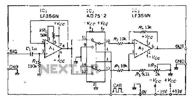
Analog switches carrier suppression amplitude modulation circuit
An analog switch (double loop, double-break) and a differential modulation amplifier are used in this circuit. The carrier control switch operates by switching contacts at specific times, inverting the input modulation wave. When the next carrier signal is applied to...
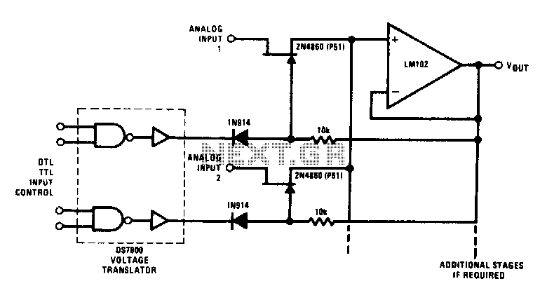
DTL-TTL controlled buffered analog switch
This analog switch utilizes the 2N4860 JFET, which features a low on-resistance of 25 ohms and minimal leakage current. The LM102 is employed as a voltage buffer in the circuit. Additionally, this configuration can be modified for use in a...
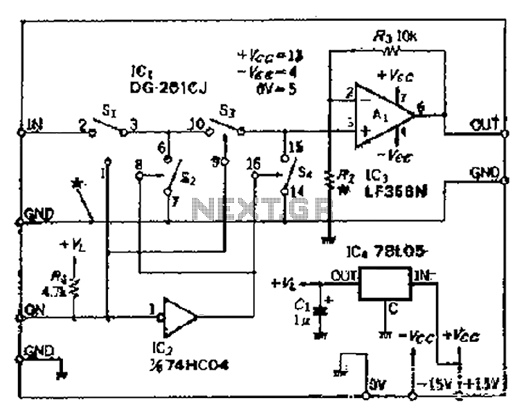
Cutting good performance signal switching circuit
Analog switches SL and SA disconnect the inverted logic signal to terminal 2. S1 and S4 are turned on, allowing capacitance between S1 and S8 to couple. S2 and S4 shunt with an on-state resistance ranging from 50 to 100...
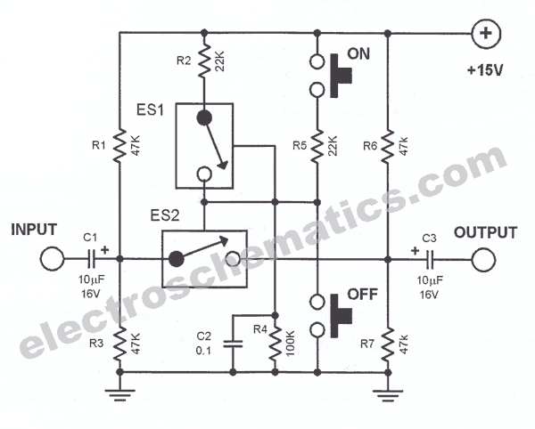
Analog Line Switch Circuit
This analog switch circuit is designed to switch an analog line on or off. It consists of two analog switches in integrated circuit (IC) form that are controlled by two pushbuttons.
The described analog switch circuit utilizes two integrated analog switches...

differential analog switch circuit
This circuit is designed for differential analog circuit switches. The FM1208 monolithic dual differential multiplexer is utilized in applications where the RDS (ON) must be closely matched. The RDS (ON) for the monolithic dual multiplexer operates with a precision better...
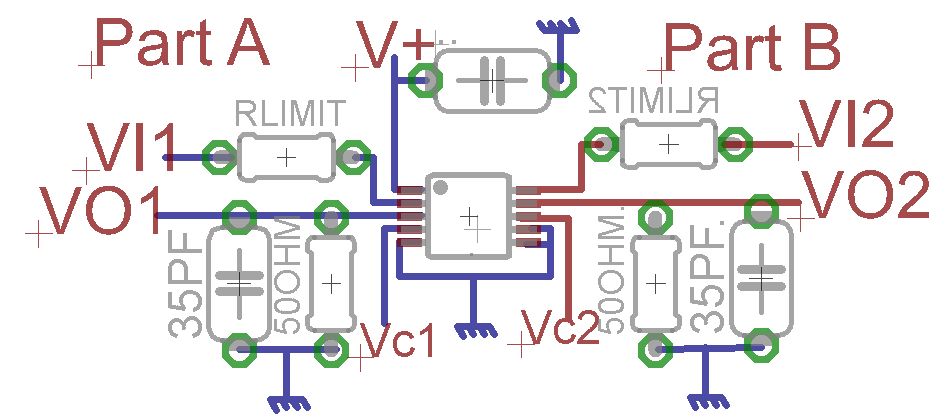
MAX4685 circuit and input current limit resistors
A request for advice regarding the connection diagram of the MAX4685 analog switch is presented. The circuit involves two inputs, VI1 and VI2.
The MAX4685 is a low-voltage, dual analog switch designed for low on-resistance and high-speed switching applications. In a...
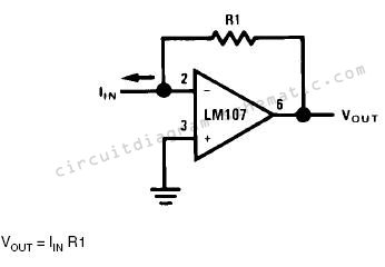
Converting current to voltage transducer circuit Using LM107
Converting current into voltage is undesirable for two reasons: first, an impedance is inserted into the measuring line, causing an error; second, amplifier offset voltage is also amplified, leading to a subsequent loss of accuracy. The use of a current-to-voltage...
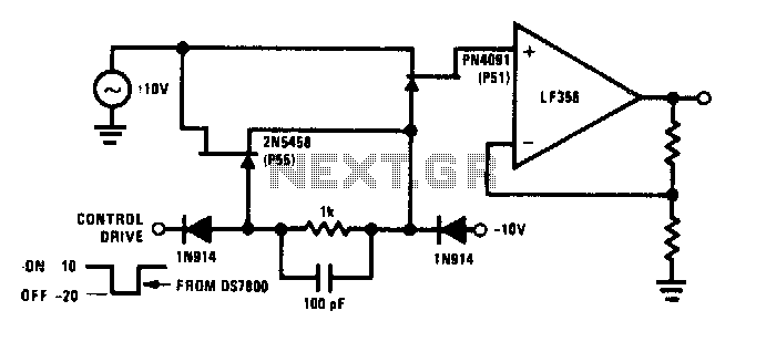
High frequency analog switch
The commutator circuit delivers low impedance gate drive to the PN4091 analog switch for both on and off drive conditions. This circuit also achieves near-ideal gate drive conditions for high-frequency signal handling by offering low AC impedance during off drive...