


Opamps and ultrasonic receiver circuitry
#ultrasonic
#receiver
#opamp
#signal processing
#sensor
#amplification
#circuit design
#audio
#transducer
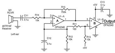
Description: Assistance is required regarding the circuits provided below. The focus is on an ultrasonic receiver circuit that utilizes two ultrasonic components.
The ultrasonic receiver circuit is designed to detect ultrasonic waves, typically in the frequency range of 20 kHz to several MHz, which are beyond the range of human hearing. This circuit is often used in applications such as distance measurement, object detection, and various forms of non-contact sensing.
The core components of an ultrasonic receiver circuit include an ultrasonic transducer, which converts ultrasonic sound waves into electrical signals. In this design, two ultrasonic transducers are employed: one for transmitting ultrasonic pulses and the other for receiving the reflected waves. The transducers are usually piezoelectric devices that respond to high-frequency signals.
The circuit may incorporate an amplifier to enhance the weak signals received by the transducer. This amplifier is typically a low-noise operational amplifier configured in a non-inverting or inverting configuration, depending on the desired gain and signal processing requirements. The output from the amplifier can be fed into a microcontroller or a comparator circuit for further processing.
Additionally, a filter may be included to eliminate noise and ensure that only signals within the desired frequency range are processed. This filter can be a band-pass filter designed to allow ultrasonic frequencies while attenuating lower and higher frequencies.
For distance measurement applications, the circuit may also feature a timing mechanism, such as a microcontroller, which calculates the time taken for the ultrasonic pulse to travel to an object and back. By knowing the speed of sound, the distance to the object can be accurately determined.
Power supply considerations are crucial in designing the circuit. A stable power source ensures consistent performance of the ultrasonic transducers and associated circuitry. Voltage regulators may be used to provide the necessary operating voltage levels for the components.
To summarize, the ultrasonic receiver circuit operates by transmitting ultrasonic pulses, receiving the echoes, amplifying the signals, filtering out noise, and processing the information to determine distance or detect objects. This makes it a versatile solution for various sensing applications in electronics.Hi! I desperately need help concerning the circuits I`ve attached below. Basically, it is an ultrasonic receiver circuit, with two ultrasonic..
The ultrasonic receiver circuit is designed to detect ultrasonic waves, typically in the frequency range of 20 kHz to several MHz, which are beyond the range of human hearing. This circuit is often used in applications such as distance measurement, object detection, and various forms of non-contact sensing.
The core components of an ultrasonic receiver circuit include an ultrasonic transducer, which converts ultrasonic sound waves into electrical signals. In this design, two ultrasonic transducers are employed: one for transmitting ultrasonic pulses and the other for receiving the reflected waves. The transducers are usually piezoelectric devices that respond to high-frequency signals.
The circuit may incorporate an amplifier to enhance the weak signals received by the transducer. This amplifier is typically a low-noise operational amplifier configured in a non-inverting or inverting configuration, depending on the desired gain and signal processing requirements. The output from the amplifier can be fed into a microcontroller or a comparator circuit for further processing.
Additionally, a filter may be included to eliminate noise and ensure that only signals within the desired frequency range are processed. This filter can be a band-pass filter designed to allow ultrasonic frequencies while attenuating lower and higher frequencies.
For distance measurement applications, the circuit may also feature a timing mechanism, such as a microcontroller, which calculates the time taken for the ultrasonic pulse to travel to an object and back. By knowing the speed of sound, the distance to the object can be accurately determined.
Power supply considerations are crucial in designing the circuit. A stable power source ensures consistent performance of the ultrasonic transducers and associated circuitry. Voltage regulators may be used to provide the necessary operating voltage levels for the components.
To summarize, the ultrasonic receiver circuit operates by transmitting ultrasonic pulses, receiving the echoes, amplifying the signals, filtering out noise, and processing the information to determine distance or detect objects. This makes it a versatile solution for various sensing applications in electronics.Hi! I desperately need help concerning the circuits I`ve attached below. Basically, it is an ultrasonic receiver circuit, with two ultrasonic..

non inverting opamp butterworth filter
The inquiry pertains to whether a specific circuit will invert the input signal. The operational amplifier (op-amp) is single-supplied with a voltage of 5V, and the input signal varies between 0V and 5V. The question arises regarding the output voltage...
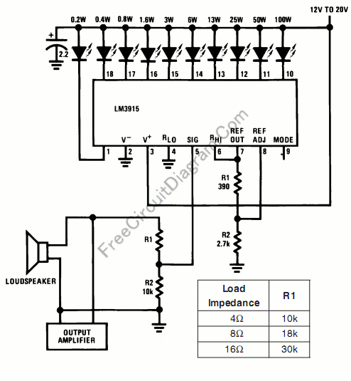
Audio Power Meter: Shows Your Audio Amplifier
This circuit allows for the measurement of the actual output power of an amplifier. It can be housed in a box to function as a measurement instrument.
The circuit for measuring amplifier output power typically includes a few essential components: a...
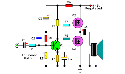
30 Watt Audio Power Amplifier
This project includes a preamplifier, tone controls, a regulated DC power supply, and delivers 18 watts into an 8-ohm load and 30 watts into a 4-ohm load.
The circuit design comprises several key components that work together to create a...
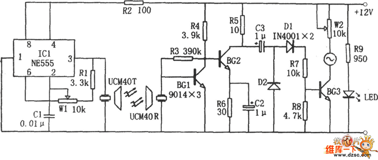
Ultrasonic Liquid Level Indicator Circuit Composed Of NE555
The image depicts an ultrasonic liquid level indicator circuit. This circuit consists of an ultrasonic transmitter circuit and a receiver circuit. The ultrasonic transmitter circuit includes a 555 timer, resistor R1, variable resistor W1, capacitor C1, and the ultrasonic transmitter...
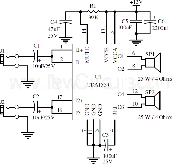
22w stereo amplifier
This document presents a 22-watt stereo audio power amplifier circuit diagram utilizing the TDA1554 integrated circuit from NXP Semiconductors (formerly Philips Semiconductors). The circuit is designed to effectively amplify stereo signals and is characterized by its simplicity and utility. It...
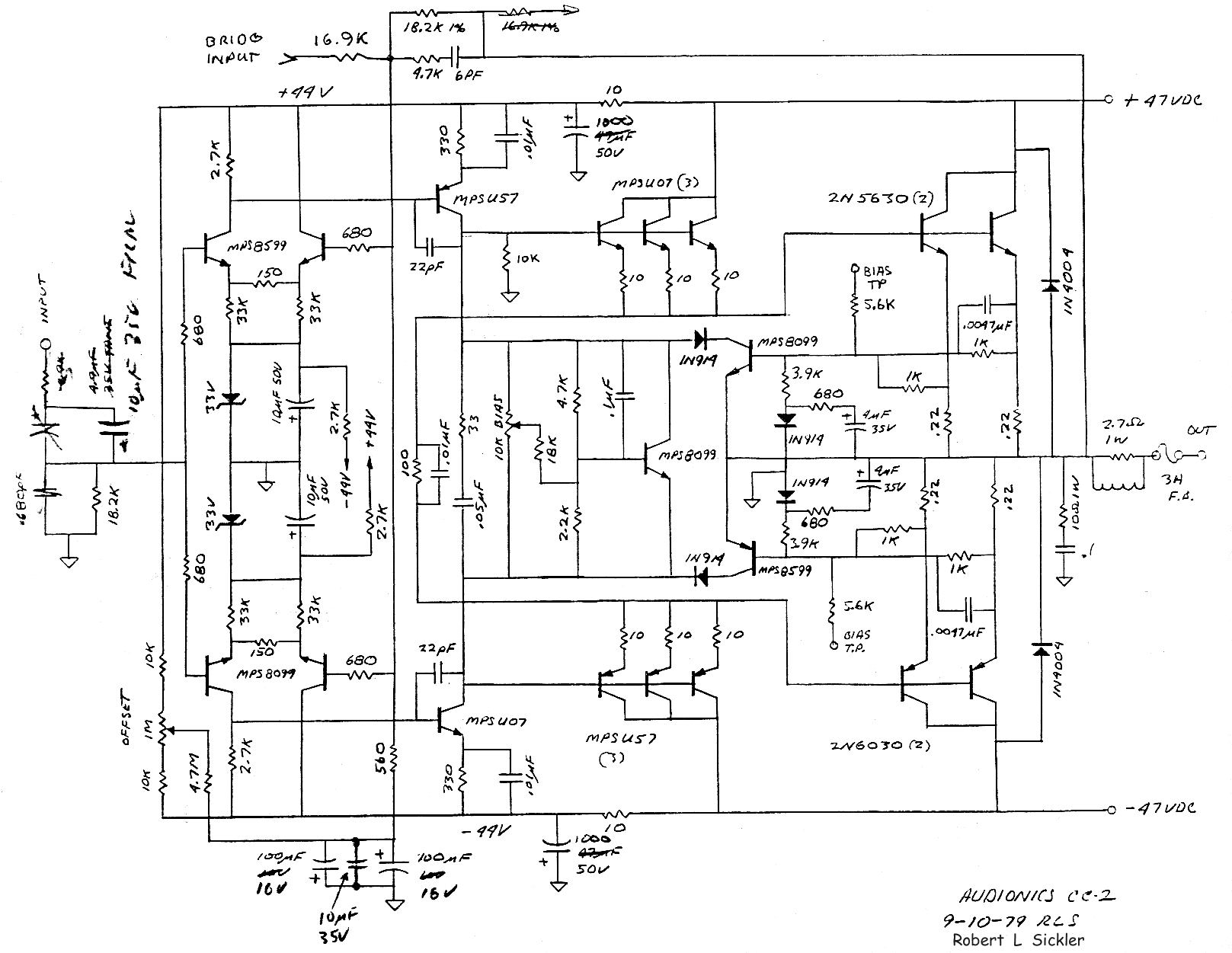
The Audionics CC-2 Amplifier
The Audionics CC-2 is named after Cliff Moulton, the chief engineer, and Charles Wood, the president of Audionics. However, the true designer of the amplifier is Bob Sickler, whose initials, "RLS," appear on the schematics. Following Bob's passing in Portland,...
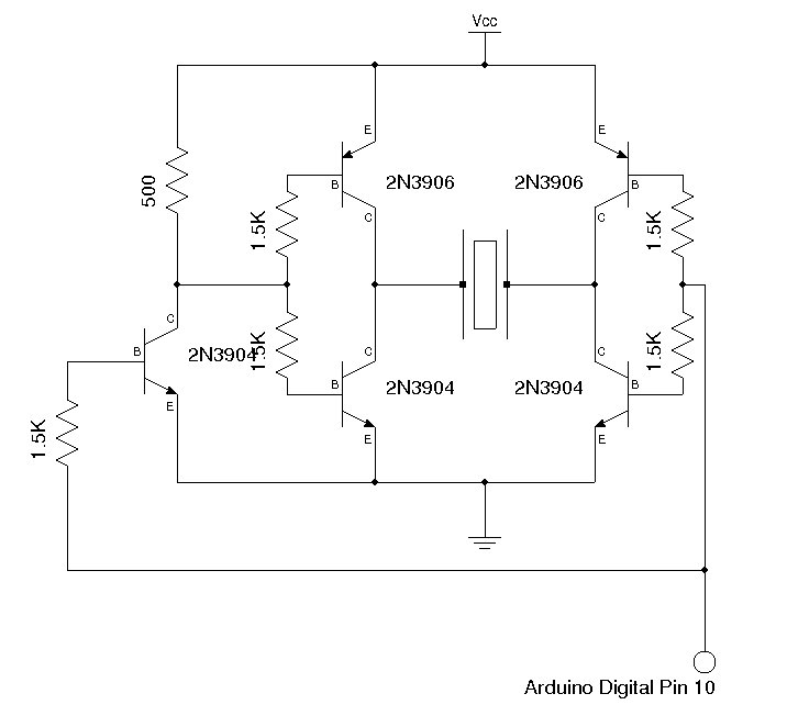
A Sensitive DIY Ultrasonic Range Sensor
Some ultrasonic range finders for a project. Most commercial sensors like Parallax's PING sensor and similar products are quite expensive, especially when multiple units are needed. Therefore, a decision was made to build the sensor independently. The theory behind ultrasonic...
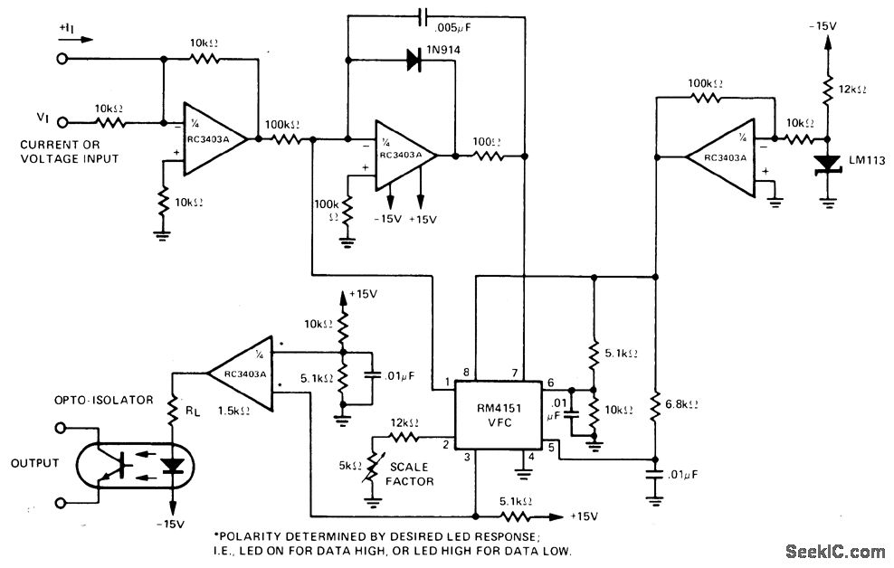
OPTICALLY COUPLED V F
The input voltage range of 0-10 V is converted to a proportional frequency at the output of an optoisolator using the RM4151 converter. This converter is paired with the RC3403A quad op-amp, which serves multiple functions including inverter, integrator, regulator,...
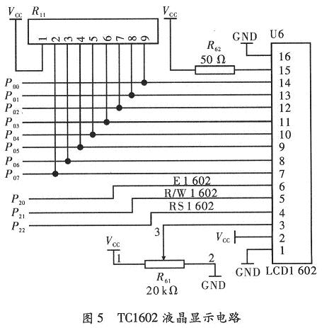
Scheme research and design of the ultrasonic range measurement system
In daily life and production, many situations such as vehicle rollback, robot obstacle avoidance, industrial well logging, and liquid level measurement in reservoirs require non-contact automatic distance measurement. Ultrasonic waves refer to sound waves produced by machinery in an elastic...