


Second-Order Polynomial Generator Circuit
#analog multiplier
#precision resistors
#quadratic polynomial
#voltage divider
#signal attenuation
#output voltage
#second-order polynomial
#coefficient adjustment
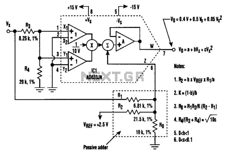
Description: A circuit utilizing a single analog multiplier and five precision resistors can produce an output voltage (Ko) that represents a second-order polynomial. This circuit implements the quadratic function. The input terminals of IC1 are configured to create a positive square term and deliver the Vr signal to the output with a scale factor of 1-10 V. The inclusion of a voltage-divider network (resistors R3 and R4) in the input signal path allows for additional attenuation adjustment of the coefficient (c) of the square term in the quadratic. Furthermore, a passive adder (resistors R1, R2, and R0) is connected to IC1's internal summing circuit to generate the polynomial's other two terms: the offset term (a) and the linear coefficient (b).
The circuit design revolves around the use of an analog multiplier, which serves as the core component for generating the quadratic output. The analog multiplier's functionality allows it to multiply two input voltages, effectively enabling the creation of the square term necessary for the second-order polynomial. The precision resistors play a crucial role in defining the coefficients of the polynomial, ensuring accurate scaling and adjustment of the output voltage.
The input signal, represented by Vr, is processed through a voltage-divider network composed of resistors R3 and R4. This network is essential for managing the input signal's amplitude and adjusting the coefficient (c) associated with the square term. By altering the resistor values, the attenuation can be finely tuned, allowing for precise control over the polynomial's characteristics.
In addition to the square term, the circuit includes a passive adder formed by resistors R1, R2, and R0. This configuration connects to the internal summing circuit of the analog multiplier, enabling the generation of the remaining two polynomial terms: the linear coefficient (b) and the constant offset term (a). The passive adder effectively combines these terms, ensuring that the output voltage accurately reflects the desired second-order polynomial.
Overall, this circuit provides a versatile and precise means of generating second-order polynomial outputs, utilizing a combination of an analog multiplier and carefully selected resistors to achieve the desired electrical characteristics. The design is well-suited for applications requiring polynomial signal generation and can be adapted for various input signal conditions by adjusting the resistor values accordingly. By using a circuit built with a single analog multiplier and five precision resistors, an output voltage (Ko) can be made to create a second- order polynomial. The circuit implements the quadratic shown. The input terminals of IC1 are connected to create a positive square term and present the Vr signal to the output with a 1-10-V scale factor.
Incorporating the voltage-divider network (resistors R3 and R4) in the input signal path provides additional attenuation adjustment for the coefficient (c) of the square term in the quadratic. Then, the passive adder (resistors Rl, R2, and Ro) is wired to ICl`s internal summing circuit to generate the polynomial`s other two terms; the offset term (a) and the linear coefficient (b).
The circuit design revolves around the use of an analog multiplier, which serves as the core component for generating the quadratic output. The analog multiplier's functionality allows it to multiply two input voltages, effectively enabling the creation of the square term necessary for the second-order polynomial. The precision resistors play a crucial role in defining the coefficients of the polynomial, ensuring accurate scaling and adjustment of the output voltage.
The input signal, represented by Vr, is processed through a voltage-divider network composed of resistors R3 and R4. This network is essential for managing the input signal's amplitude and adjusting the coefficient (c) associated with the square term. By altering the resistor values, the attenuation can be finely tuned, allowing for precise control over the polynomial's characteristics.
In addition to the square term, the circuit includes a passive adder formed by resistors R1, R2, and R0. This configuration connects to the internal summing circuit of the analog multiplier, enabling the generation of the remaining two polynomial terms: the linear coefficient (b) and the constant offset term (a). The passive adder effectively combines these terms, ensuring that the output voltage accurately reflects the desired second-order polynomial.
Overall, this circuit provides a versatile and precise means of generating second-order polynomial outputs, utilizing a combination of an analog multiplier and carefully selected resistors to achieve the desired electrical characteristics. The design is well-suited for applications requiring polynomial signal generation and can be adapted for various input signal conditions by adjusting the resistor values accordingly. By using a circuit built with a single analog multiplier and five precision resistors, an output voltage (Ko) can be made to create a second- order polynomial. The circuit implements the quadratic shown. The input terminals of IC1 are connected to create a positive square term and present the Vr signal to the output with a 1-10-V scale factor.
Incorporating the voltage-divider network (resistors R3 and R4) in the input signal path provides additional attenuation adjustment for the coefficient (c) of the square term in the quadratic. Then, the passive adder (resistors Rl, R2, and Ro) is wired to ICl`s internal summing circuit to generate the polynomial`s other two terms; the offset term (a) and the linear coefficient (b).
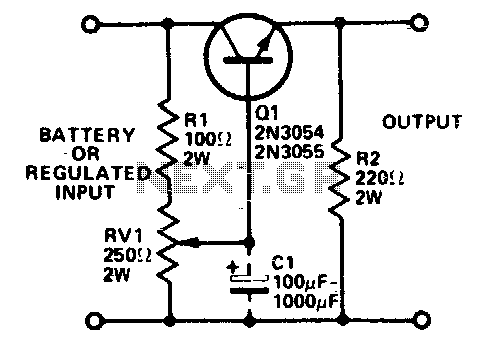
Regulated voltage divider
Integrated circuits (ICs) that require 3 or 6 volts can be powered from a battery or a fixed regulated supply with a higher voltage using the circuit illustrated. It is essential to mount the transistor on a heatsink, as significant...
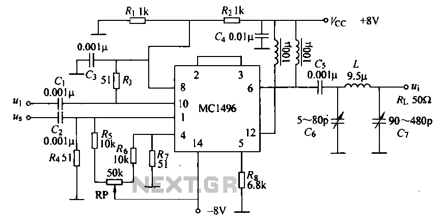
Mixing analog multiplier integrated circuit MC1496
Currently, a high-quality communications receiver utilizes diode ring mixers and a double differential pair balanced modulator, configured as an analog multiplier (MC1496). The mixer circuits are illustrated in the accompanying figure. The local oscillator (LO) voltage and the input signal...
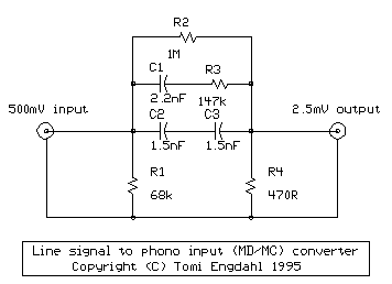
Line level to phono input
The circuit performs two functions: signal level attenuation and inverse RIAA filtering. Signal attenuation is required to convert a 500 mV signal to a 2.5 mV signal. Inverse-RIAA filtering is necessary to achieve a flat frequency response, similar to the...
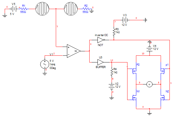
Circuit clarification needed
Can someone please help explain how this circuit works? I am confident that I understand how the voltage divider network operates.
The circuit in question likely includes a voltage divider configuration, which is a fundamental concept in electronics used to produce...
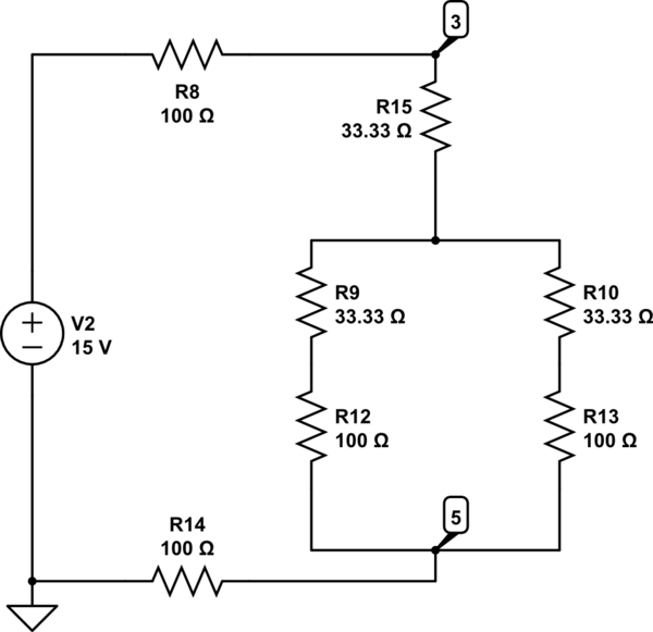
When use Voltage divider in circuit analysis
The Delta configuration of resistors R2, R3, and R4 is converted to a Wye (Y) configuration. This conversion is necessary because a voltage divider is typically employed in series circuits. The aim is to determine the total resistance in this...
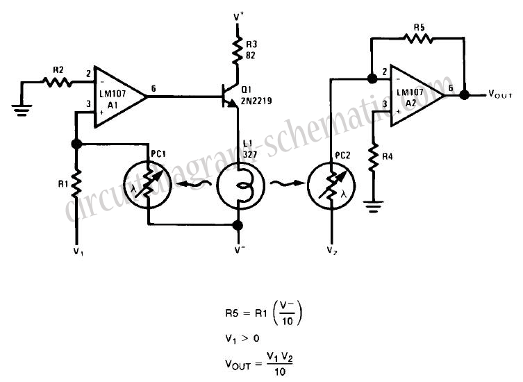
Simple Analog Multiplier Circuit Using LM107
This circuit is a simple analog multiplier. The operation of the circuit can be understood by considering A2 as a controlled gain amplifier. It involves components such as an analog multiplier, a log-antilog circuit, and a summing junction, along with...
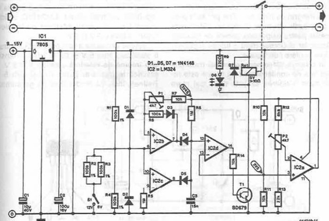
autoconnect disconnect battery charger
A simple battery charger is designed to disconnect the battery when the charge voltage reaches its nominal level and reconnect when the battery voltage drops below a predefined threshold. This is achieved using a circuit diagram that incorporates a voltage...
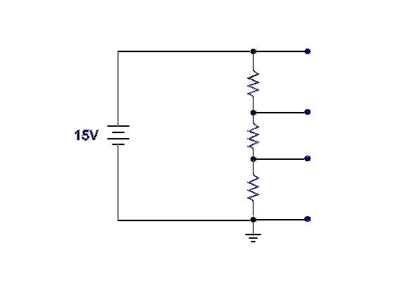
Reading a voltage divider schematic
Ground serves as a reference point for the voltage divider, with each successive point above ground indicating the voltage drop across the circuit. For example, with a 15-volt input and 5K ohm resistors, the voltage taps would measure 5, 10,...
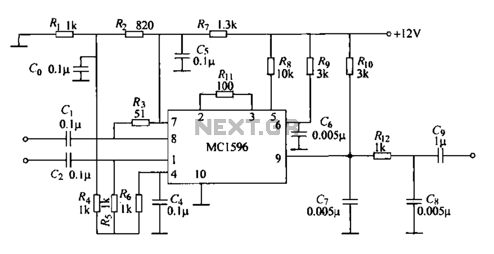
Consisting of integrated analog multiplier MC1596 synchronous detector
The circuit features an integrated analog multiplier, the MC1596, functioning as a synchronous detector. It is designed to demodulate amplitude-modulated signals sourced from an integrated circuit. The output signal is derived from the O pin, where a local carrier frequency...