


Simple Analog Multiplier Circuit Using LM107
#analog multiplier
#LM107
#controlled gain amplifier
#log-antilog circuit
#inverting amplifier
#summing junction
#photoconductors
#op-amp
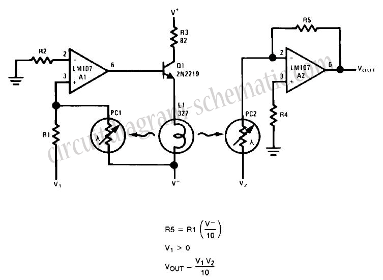
Description: This circuit is a simple analog multiplier. The operation of the circuit can be understood by considering A2 as a controlled gain amplifier. It involves components such as an analog multiplier, a log-antilog circuit, and a summing junction, along with inverting amplifiers and photoconductors.
The described circuit functions as an analog multiplier, which is essential in various applications such as signal processing and control systems. The core of the circuit utilizes a controlled gain amplifier, designated as A2, which adjusts the gain based on the input signals. This enables the circuit to perform multiplication of two analog signals effectively.
In this configuration, the analog multiplier can be realized using operational amplifiers (op-amps) configured in a specific arrangement. The log-antilog circuit is crucial for achieving the multiplication function, as it converts the input voltages into logarithmic values, allowing for the addition of these logarithmic signals. The summing junction, typically formed by an inverting amplifier, facilitates the addition of the logarithmic inputs.
Photoconductors may be integrated into the circuit to enable light-controlled operations, where the resistance of the photoconductor changes with light intensity, thereby affecting the gain of the amplifier. This feature allows for the modulation of the output based on ambient light conditions, making the circuit versatile for applications in light-sensitive environments.
Overall, the design and implementation of this analog multiplier circuit showcase the principles of analog signal processing, leveraging the characteristics of operational amplifiers and logarithmic functions to achieve accurate multiplication of input signals.This circuit a simple analog multiplier, the circuit operation may be understood by considering A2 as a controlled gain amplifier, Analog Multiplier, Multiplier Circuit, log-antilog circuit, analog multiplication, controlled gain amplifier, summing junction, photoconductors, inverting amplifier,.
The described circuit functions as an analog multiplier, which is essential in various applications such as signal processing and control systems. The core of the circuit utilizes a controlled gain amplifier, designated as A2, which adjusts the gain based on the input signals. This enables the circuit to perform multiplication of two analog signals effectively.
In this configuration, the analog multiplier can be realized using operational amplifiers (op-amps) configured in a specific arrangement. The log-antilog circuit is crucial for achieving the multiplication function, as it converts the input voltages into logarithmic values, allowing for the addition of these logarithmic signals. The summing junction, typically formed by an inverting amplifier, facilitates the addition of the logarithmic inputs.
Photoconductors may be integrated into the circuit to enable light-controlled operations, where the resistance of the photoconductor changes with light intensity, thereby affecting the gain of the amplifier. This feature allows for the modulation of the output based on ambient light conditions, making the circuit versatile for applications in light-sensitive environments.
Overall, the design and implementation of this analog multiplier circuit showcase the principles of analog signal processing, leveraging the characteristics of operational amplifiers and logarithmic functions to achieve accurate multiplication of input signals.This circuit a simple analog multiplier, the circuit operation may be understood by considering A2 as a controlled gain amplifier, Analog Multiplier, Multiplier Circuit, log-antilog circuit, analog multiplication, controlled gain amplifier, summing junction, photoconductors, inverting amplifier,.
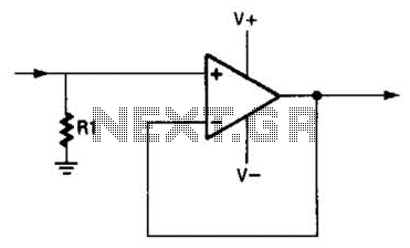
Noninverted Unity-Gain Amplifier Circuit
An operational amplifier (op amp) can function as a unity gain amplifier by connecting its output to its inverting input as illustrated. The load resistance (Rl) should be sufficiently low to prevent the op amp's bias current from introducing a...
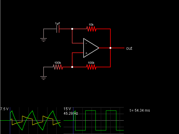
Relaxation Oscillator
This circuit is an oscillator that generates a square wave. The operational amplifier (op-amp) begins with its two inputs in an undefined state, starting with the non-inverting input slightly higher than the inverting input. The op-amp significantly amplifies this difference,...
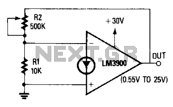
Variable-Voltage Reference Source
The non-inverting terminal of the operational amplifier (op-amp) is grounded, and the circuit utilizes the voltage at the inverting terminal as a reference. The voltage gain of the circuit is determined by the ratio of resistors R2 to R. When...
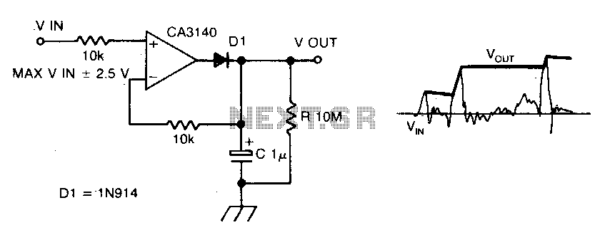
Precision peakvoltage detector
The circuit employs negative feedback exclusively for positive signals. The inverting input receives feedback only when diode D1 is forward biased, which occurs solely with positive input signals. As the positive input signal increases, the output of the operational amplifier...
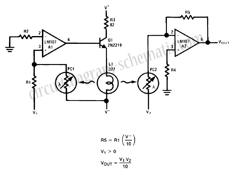
Simple Analog Multiplier Circuit Using LM107
This circuit is a simple analog multiplier. The operation of the circuit can be understood by considering A2 as a controlled gain amplifier that amplifies V2, with its gain dependent on the ratio of the resistance of PC2 to R5....
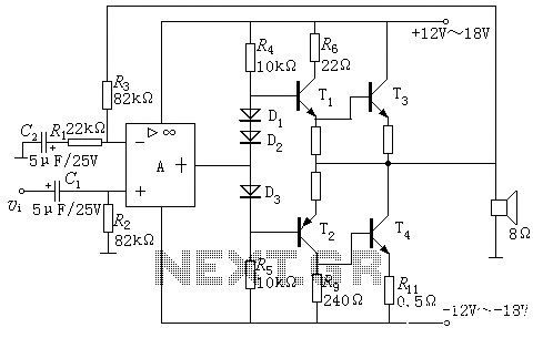
Integrated operational amplifier drives the power amplifier OCL
In a power supply circuit with a rating of 15V and a 10W power load, there are notable differences between two circuit configurations. The first configuration (A) uses discrete components in place of an integrated operational amplifier for the driving...
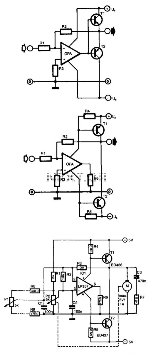
Op Amp Power Driver
Frequently, the output current of an operational amplifier is inadequate for applications such as driving a small motor or loudspeaker. This issue is typically resolved by adding an emitter follower to the circuit. However, this configuration does not allow the...
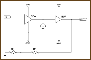
Biasing Op-Amps into Class A
"Class A" refers to configuring an amplifier so that its output devices remain turned on all the time. This reduces thermal variation and eliminates crossover distortion, which makes the chip perform better. To bias an op-amp into class A, you...
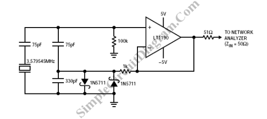
Op-Amp Colpitts Oscillator
A Colpitts oscillator can be implemented using an operational amplifier, provided that the op-amp has an appropriate bandwidth. An example of such a circuit can utilize the LT1190 or LT1191.
The Colpitts oscillator is a type of electronic oscillator that generates...