


Ultrasonic_filter
#LM833
#filter
#ultrasonic
#Bessel filter
#4th-order
#signal processing
#audio
#high-pass
#low-pass
#precision components
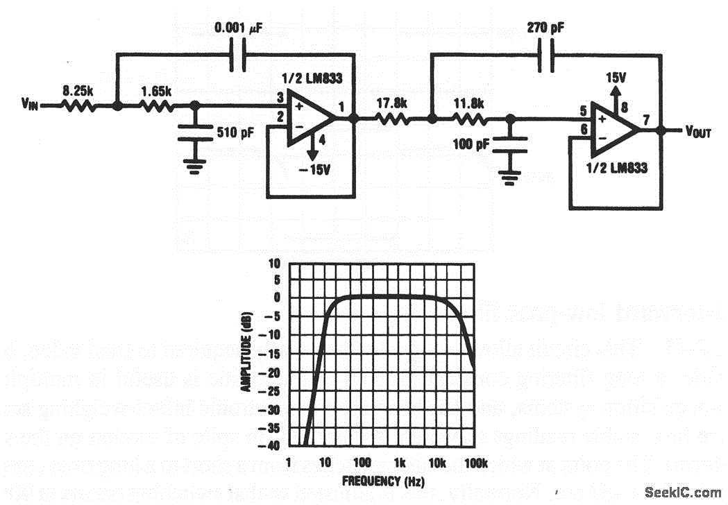
Description: This circuit illustrates both sections of an LM833 configured as a filter to eliminate unwanted ultrasonic signals. The filter exhibits a 4th-order Bessel characteristic, with a -3 dB frequency approximately at 40 kHz. It is recommended that resistors and capacitors used in this circuit have a tolerance of 1%. This circuit can be cascaded with the circuit shown in Fig. 7-43, with the low-pass filter preceding the high-pass filter.
The LM833 is a dual operational amplifier that is well-suited for filter applications due to its low noise and high performance. In this configuration, the circuit is designed to provide a precise filtering effect, specifically aimed at attenuating signals above 40 kHz while maintaining signal integrity below this threshold. The 4th-order Bessel filter characteristic is chosen for its maximally flat group delay, which is essential in applications where phase distortion must be minimized.
The circuit consists of two primary sections: the low-pass filter and the high-pass filter. The low-pass filter section is designed to allow signals below the cutoff frequency of 40 kHz to pass through while attenuating higher frequencies. This is achieved through a combination of resistors and capacitors arranged in a specific topology that defines the filter's response.
The high-pass filter section, on the other hand, is configured to block lower frequencies while allowing higher frequencies to pass. By cascading these two filters, the overall circuit can effectively reject undesired ultrasonic signals while preserving the desired audio frequency range.
For optimal performance, it is crucial to use components with a tolerance of 1% to ensure that the filter characteristics remain consistent and predictable. Variations in component values can significantly affect the filter's response, leading to undesirable performance.
In summary, this circuit serves as a robust solution for applications requiring the rejection of ultrasonic frequencies, utilizing the LM833 operational amplifier in a well-defined filter configuration that can be integrated with additional filtering stages as necessary.This circuit shows both sections of an LM833 that is connected as a filter to reject undesired ultrasonic signals. The filter characteristic is 4th-order Bessel with the -3-dB frequency at about 40 kHz. Resistors and capacitors should be 1%-tolerance components. This circuit can be cascaded with that of Fig. 7-43 (with the low-pass preceding the high-pass) t..
The LM833 is a dual operational amplifier that is well-suited for filter applications due to its low noise and high performance. In this configuration, the circuit is designed to provide a precise filtering effect, specifically aimed at attenuating signals above 40 kHz while maintaining signal integrity below this threshold. The 4th-order Bessel filter characteristic is chosen for its maximally flat group delay, which is essential in applications where phase distortion must be minimized.
The circuit consists of two primary sections: the low-pass filter and the high-pass filter. The low-pass filter section is designed to allow signals below the cutoff frequency of 40 kHz to pass through while attenuating higher frequencies. This is achieved through a combination of resistors and capacitors arranged in a specific topology that defines the filter's response.
The high-pass filter section, on the other hand, is configured to block lower frequencies while allowing higher frequencies to pass. By cascading these two filters, the overall circuit can effectively reject undesired ultrasonic signals while preserving the desired audio frequency range.
For optimal performance, it is crucial to use components with a tolerance of 1% to ensure that the filter characteristics remain consistent and predictable. Variations in component values can significantly affect the filter's response, leading to undesirable performance.
In summary, this circuit serves as a robust solution for applications requiring the rejection of ultrasonic frequencies, utilizing the LM833 operational amplifier in a well-defined filter configuration that can be integrated with additional filtering stages as necessary.This circuit shows both sections of an LM833 that is connected as a filter to reject undesired ultrasonic signals. The filter characteristic is 4th-order Bessel with the -3-dB frequency at about 40 kHz. Resistors and capacitors should be 1%-tolerance components. This circuit can be cascaded with that of Fig. 7-43 (with the low-pass preceding the high-pass) t..
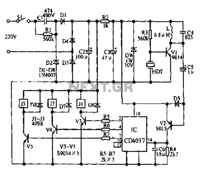
Asia ultrasonic remote control fan speed control circuit diagram
Fans can be controlled remotely with a switch that allows for speed adjustments, and this remote control can also be integrated with other household switches. Its primary feature is the use of a sub-transmission ultrasonic transmitter, which operates without directional...
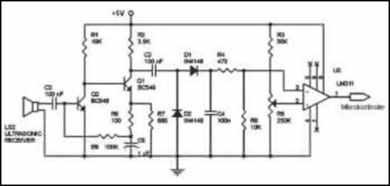
Ultrasonic Wave Receiver Circuit Schematic Diagram
Ultrasonic receivers detect an ultrasonic signal emitted by an ultrasonic transmitter at a specific frequency. The received signal is filtered using a band-pass filter circuit that allows only the predetermined frequency range to pass. The output signal is then amplified...
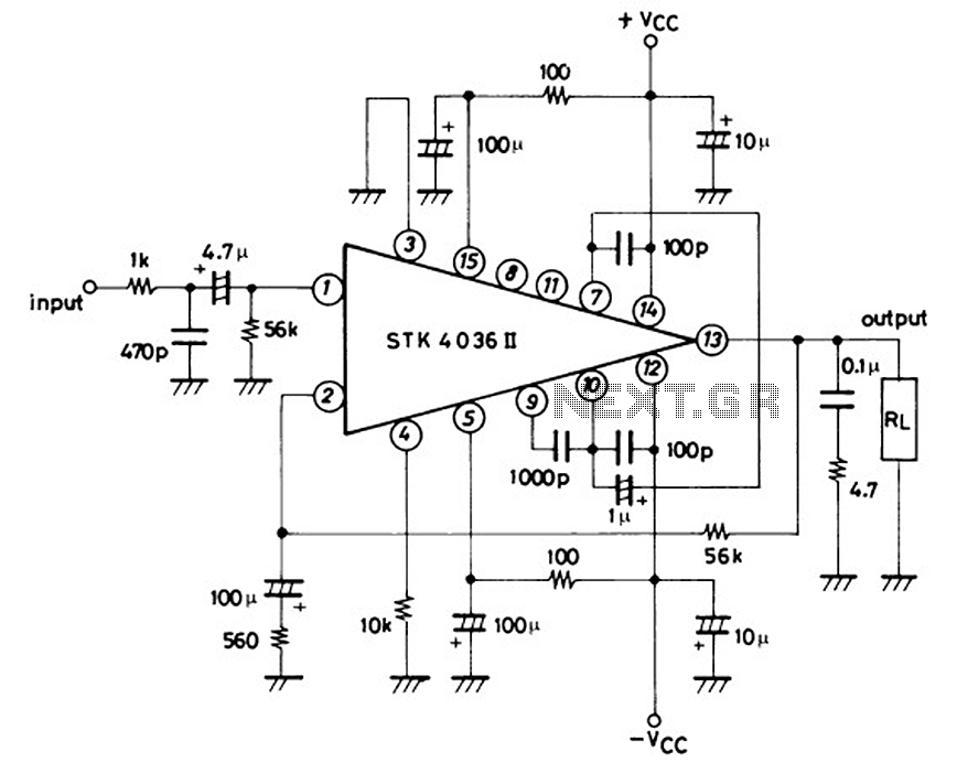
Schematic Diagram 50W TK4036II baseed Stereo Power Amplifier Circuitand explanation
This is a 50-watt audio power amplifier circuit based on the single IC STK4036II. A heatsink is required to prevent overheating of the IC. The amplifier circuit provides good sound quality at an affordable price and is easy to construct...
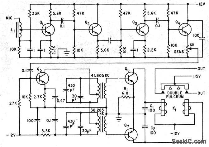
ULTRASONIC CONTROL RECEIVER
A five-stage amplifier consisting of transistors Q1 through Q5 amplifies the control signals at frequencies of 38.285 kHz and 41.805 kHz. Transistors Q6 and Q7 function as class B detector-amplifiers, thereby eliminating the need for separate diode detectors. The desired...
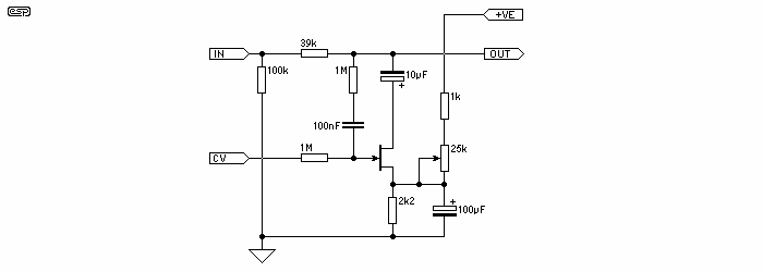
Fast Audio Peak Limiter
The circuit devised by Phil Allison still has some input voltage limitations, since it is based on a FET. Junction FET VCAs also create considerable distortion, with the worst of it appearing when the signal is attenuated by 6dB. The...
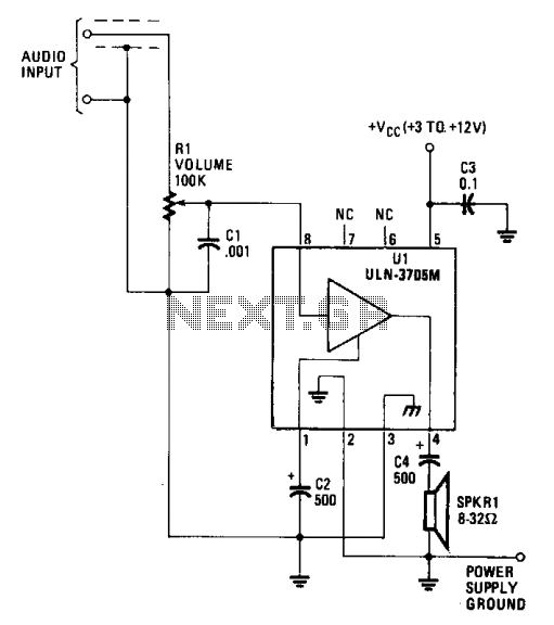
Low power audio amplifier
The amplifier functions with supply voltages up to 12 volts and can operate at lower voltages as low as 1.8 volts while maintaining acceptable distortion levels, albeit with reduced volume. Its power requirements make it suitable for applications powered by...
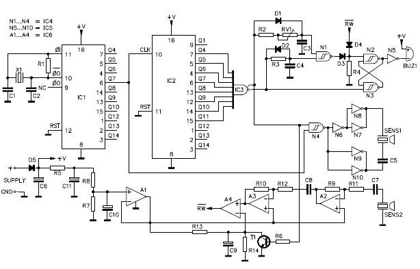
Ultrasonic parking sonar circuit design project
A simple ultrasonic parking sonar electronic project can be designed using this schematic circuit. This ultrasonic parking sonar project features an adjustable detection range from 5 cm to 1.5 meters and a detection angle of 5 degrees. The circuit operates...
Automatic Loudness Control
Simple add-on module, Switchable "Control-flat" option. In order to obtain good audio reproduction at different listening levels, a different tone control...
The described module is a straightforward add-on designed to enhance audio reproduction across various listening levels. The "Control-flat" option allows...

25W HiFi Audio Amplifier with MOSFET
This is a high-fidelity, high-quality audio amplifier circuit diagram. A pre-amplifier is not required. Component list: R1, R4 = 47K 1/4W resistors; R2 = 4.7K 1/4W resistor; R3 = 1.5K 1/4W resistor; R5 = 390Ω 1/4W resistor; R6 = 470Ω...