


chaos
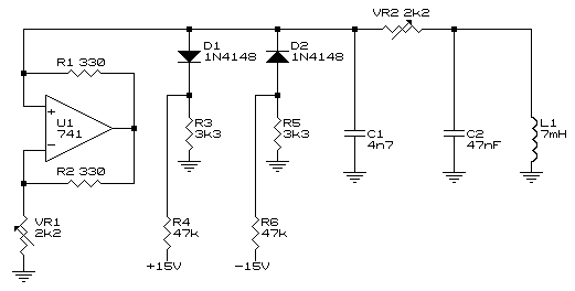
Description: The same equations can also be applied to D2, R5, and R6, which form the negative non-linearity of the circuit, although all the signs should be inverted for the threshold voltage equation. Between the positive and negative threshold voltages, only the negative resistance will be seen by the circuit. If the voltage moves out of this range, either D1 or D2 will start to conduct, which will insert a resistance in parallel with the negative resistance, effectively decreasing the value of the negative resistance. It is not easy to build this circuit; the values are quite critical, and controlling any parameter via a computer is challenging. For this reason, a computer simulation program for the Chua circuit has been developed. This program allows for parameter adjustments, displays graphs in various formats, and enables the saving of waveforms as .WAV files. The parameters L, C1, C2, and G represent the linear parts of the circuit and correspond to L1, C1, C2, and VR2 in the schematic. Bp1 and Bp2 are the parameters for the non-linear negative resistance, where Bp1 and Bp2 denote the negative and positive threshold points. m0 represents the resistance if the voltage is below Bp1, m1 if the voltage is between the two thresholds, and m2 if the voltage is above Bp2. The following set of screenshots displays graphs of Vc2 versus Vc1 for different values of C2. In the graph below, the value of C2 is set to 0.4. At this point, there is not enough gain in the circuit to sustain oscillation, and the oscillation dies out. The circuit has been built based on the schematic provided. Below is a photo of the circuit. A variable inductor coil has been salvaged from an old TV's convergence circuit.
The circuit under discussion is a Chua circuit, known for its ability to exhibit chaotic behavior. The critical components include two diodes (D1 and D2), resistors (R5 and R6), and a variable inductor, which together establish the circuit's non-linear characteristics. The negative resistance region is crucial for the oscillation behavior, as it allows for energy storage and release, leading to oscillatory dynamics.
The diodes D1 and D2 are strategically placed to manage the conduction paths based on the voltage levels, creating a piecewise linear characteristic for the circuit. The negative resistance is defined between the threshold voltages set by Bp1 and Bp2, where the circuit behaves differently based on the input voltage. When the voltage exceeds Bp2, the circuit transitions to a state where D2 conducts, effectively reducing the negative resistance and damping the oscillation.
The simulation program developed allows for comprehensive analysis and experimentation with the Chua circuit parameters. By adjusting L, C1, C2, and G, users can observe the impact on circuit behavior, particularly the oscillation frequency and amplitude. The graphs generated by the simulation provide insight into the relationship between the capacitor voltages Vc1 and Vc2, illustrating the dynamic behavior of the circuit under varying conditions.
In practical applications, the variable inductor coil sourced from an old TV demonstrates the potential for reusing components in circuit design while maintaining functionality. The critical nature of component values in achieving the desired oscillatory behavior emphasizes the importance of precision in circuit design and the utility of simulation tools in optimizing performance.The same equations can also be applied to D2, R5 and R6 which forms the negative non-linearity of the circuit, although all the signs should be inverted for the threshold voltage equation. Between the positive and negative threshold voltages, only the negative resistance will be seen by the circuit.
If the voltage moves out of this range, either D 1 or D2 will start to conduct, which will insert a resistance parallel with the negative resistance, which will in effect decrease the negative resistance`s value. It is not that easy to build this circuit, the values are quite critical and it is not that easy to control any parameter via a computer.
For this reason I have decided to write a computer simulation program for the Chua circuit. This program lets you adjust all the parameters, displays graphs in various formats, and it is also possible to save waveforms as. WAV files. The parameters L, C1, C2, G are the linear parts of the circuit and represents L1, C1, C2 and VR2 in the schematic.
Bp1, Bp2, m0, m1 and m2 are the parameters for the non-linear negative resistance. Bp1 and Bp2 are the negative and positive threshold points. m0 is the resistance if the voltage is below Bp1, m1 if the voltage is between the two thresholds, and m2 if the voltage is above Bp2. The following set of screenshots displays graphs of Vc2 versus Vc1 for different values of C2. In the graph below the value of C2 is set to 0. 4. At this point there is not enough gain in the circuit to sustain oscillation and the oscillation dies out.
I have build the circuit based on the schematic at the top. Below is a photo of the circuit. I got the variable inductor coil out of an old TV`s convergence circuit.
The circuit under discussion is a Chua circuit, known for its ability to exhibit chaotic behavior. The critical components include two diodes (D1 and D2), resistors (R5 and R6), and a variable inductor, which together establish the circuit's non-linear characteristics. The negative resistance region is crucial for the oscillation behavior, as it allows for energy storage and release, leading to oscillatory dynamics.
The diodes D1 and D2 are strategically placed to manage the conduction paths based on the voltage levels, creating a piecewise linear characteristic for the circuit. The negative resistance is defined between the threshold voltages set by Bp1 and Bp2, where the circuit behaves differently based on the input voltage. When the voltage exceeds Bp2, the circuit transitions to a state where D2 conducts, effectively reducing the negative resistance and damping the oscillation.
The simulation program developed allows for comprehensive analysis and experimentation with the Chua circuit parameters. By adjusting L, C1, C2, and G, users can observe the impact on circuit behavior, particularly the oscillation frequency and amplitude. The graphs generated by the simulation provide insight into the relationship between the capacitor voltages Vc1 and Vc2, illustrating the dynamic behavior of the circuit under varying conditions.
In practical applications, the variable inductor coil sourced from an old TV demonstrates the potential for reusing components in circuit design while maintaining functionality. The critical nature of component values in achieving the desired oscillatory behavior emphasizes the importance of precision in circuit design and the utility of simulation tools in optimizing performance.The same equations can also be applied to D2, R5 and R6 which forms the negative non-linearity of the circuit, although all the signs should be inverted for the threshold voltage equation. Between the positive and negative threshold voltages, only the negative resistance will be seen by the circuit.
If the voltage moves out of this range, either D 1 or D2 will start to conduct, which will insert a resistance parallel with the negative resistance, which will in effect decrease the negative resistance`s value. It is not that easy to build this circuit, the values are quite critical and it is not that easy to control any parameter via a computer.
For this reason I have decided to write a computer simulation program for the Chua circuit. This program lets you adjust all the parameters, displays graphs in various formats, and it is also possible to save waveforms as. WAV files. The parameters L, C1, C2, G are the linear parts of the circuit and represents L1, C1, C2 and VR2 in the schematic.
Bp1, Bp2, m0, m1 and m2 are the parameters for the non-linear negative resistance. Bp1 and Bp2 are the negative and positive threshold points. m0 is the resistance if the voltage is below Bp1, m1 if the voltage is between the two thresholds, and m2 if the voltage is above Bp2. The following set of screenshots displays graphs of Vc2 versus Vc1 for different values of C2. In the graph below the value of C2 is set to 0. 4. At this point there is not enough gain in the circuit to sustain oscillation and the oscillation dies out.
I have build the circuit based on the schematic at the top. Below is a photo of the circuit. I got the variable inductor coil out of an old TV`s convergence circuit.
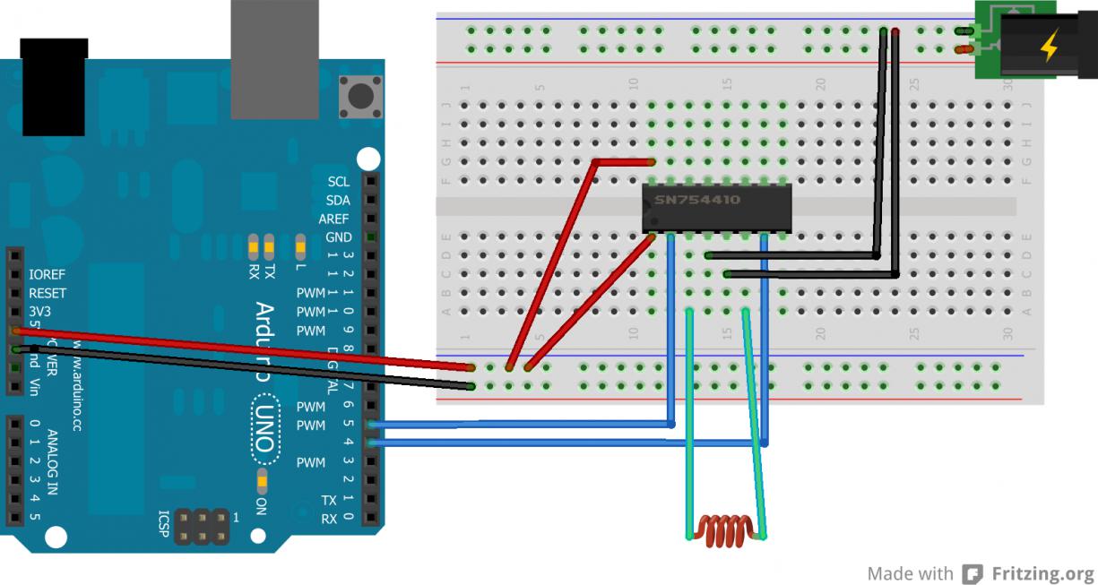
diodes on electromechanical vane display
A newcomer to electronics has recently acquired several electromechanical seven-segment vane displays and seeks assistance.
Electromechanical seven-segment vane displays are devices commonly used for visual representation of numerical data. They consist of a series of segments arranged in a figure-eight pattern,...
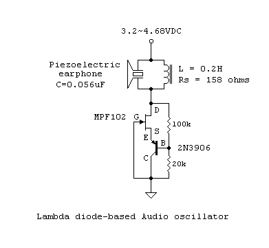
Oscillations and Regenerative Amplification using Negative Resistance
The usual procedure for producing sustained oscillations in tuned L-C networks involves overcoming circuit losses through designed-in positive feedback or regeneration. During the circuit's on-transient, oscillations build up, triggered by the thermal noise of circuit elements. Two possible situations may...
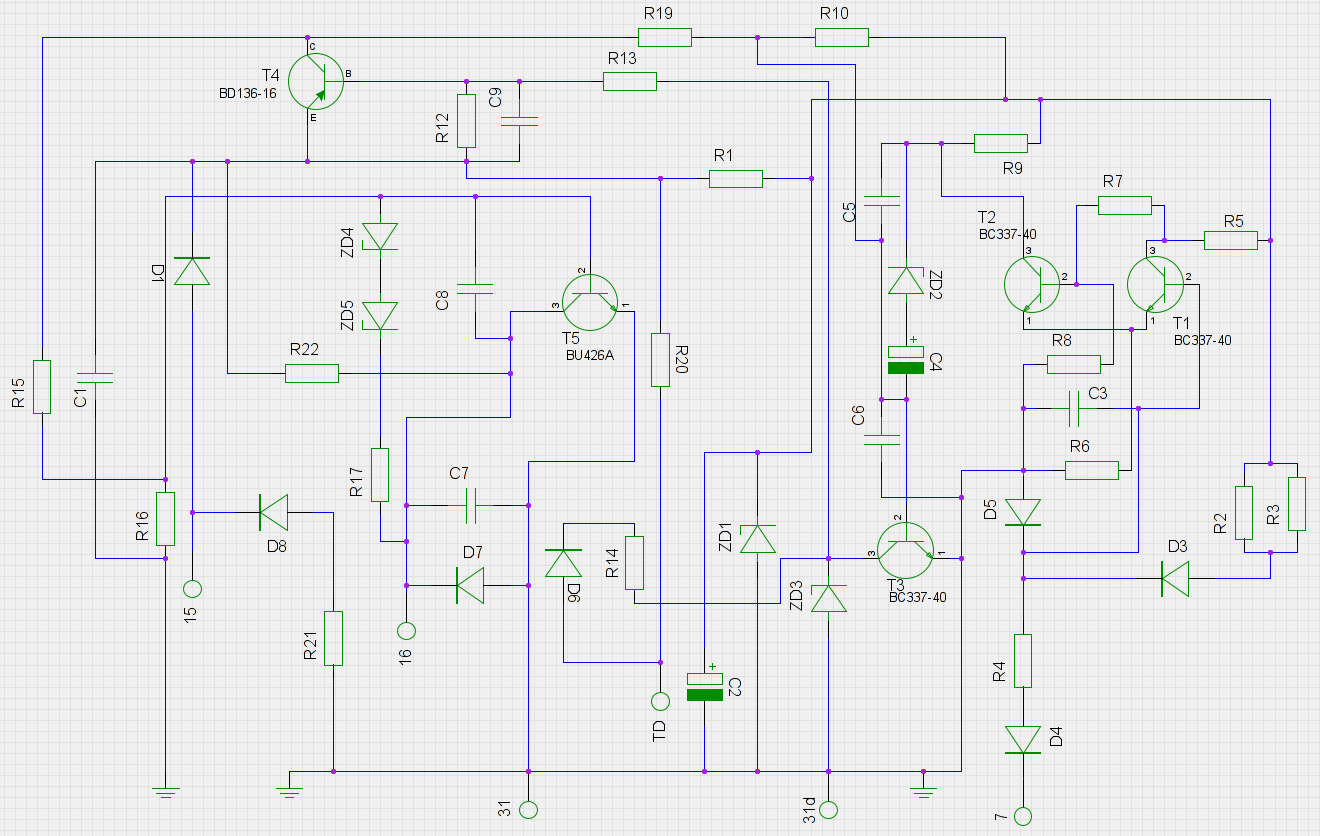
pcb Need help with identifying diodes in a 1970s automotive circuit
An old ignition module from a 1978 W116 model Mercedes-Benz is being reverse-engineered. The original circuit diagram is not available, so a new one has been created based on the printed circuit board (PCB). The circuit has been assessed to...
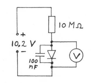
Diodes for crystal receivers
Diodes with a low voltage drop also exhibit a high reverse current (leakage current), which places a heavier load on the detector circuit, reducing the quality factor (Q) of the circuit and consequently lowering the voltage across the LC circuit....
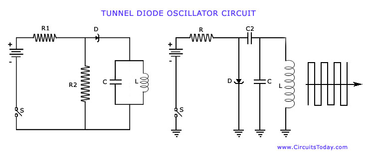
Negative Resistance Oscillators-WorkingTypesCircuitsCharacteristics
The operation of Negative Resistance Oscillators, including types such as Dynatron and Tunnel Diode Oscillator, along with their characteristics and circuit diagrams, is explained.
Negative resistance oscillators are electronic circuits that exploit the phenomenon of negative resistance to generate oscillations. These...
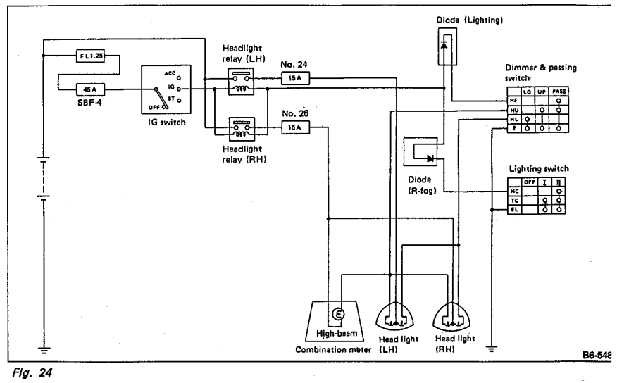
Whats the purpose of the diodes in this circuit
Understanding the headlight wiring in a car involves examining the purpose of two diodes in the circuit diagram. The circuit allows for two independent methods of activating the light relays: through the light switch or by flashing the high beams....
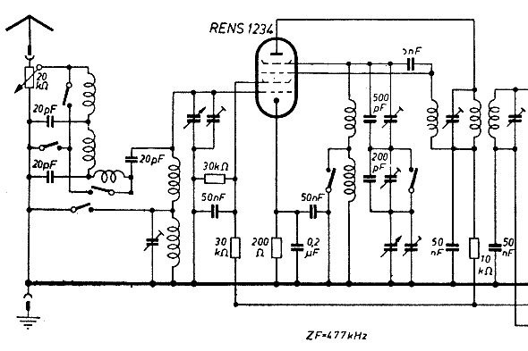
Negative Resistance Oscillators
The schematic of the mixer section illustrates an oscillator. The oscillator's LC circuit has only two connections to the valve and does not include a tap or tickler coil. Oscillations will only occur if the tube provides a negative resistance...
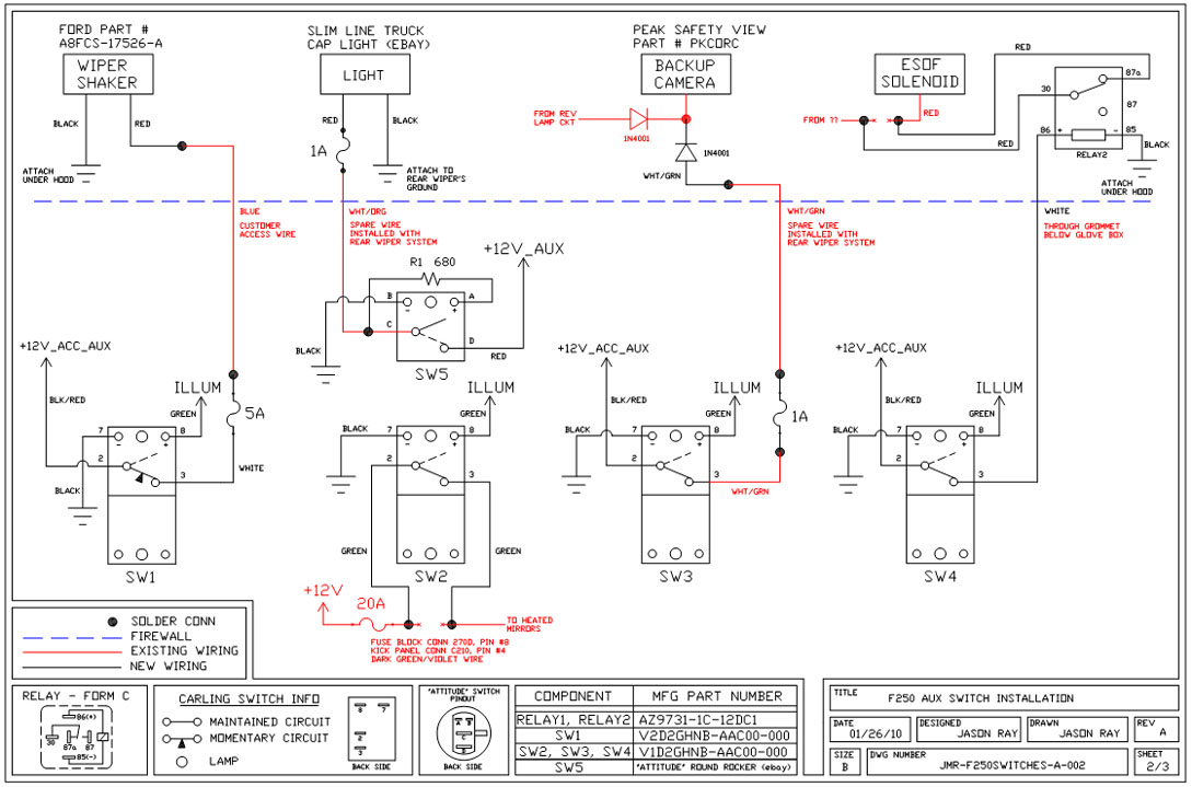
Uplifter Switches
A +12V switched wire was routed back to the camera wiring and connected at the same point as the reverse lights. This configuration allows either the reverse lights or the switch to activate the camera. The critical component in this...
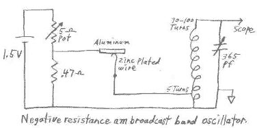
Negative Resistance Oscillator with Tunnel Diode
This circuit can be easily powered from a 1.5 volt battery. One characteristic of N type negative resistance devices is that they typically require a very low bias source resistance in order to keep the bias voltage stable within the...