


F007 excellent performance of low-frequency signal generator circuit
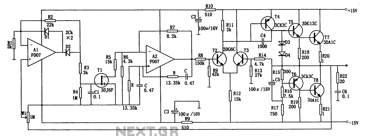
Description: The low-frequency signal generating circuit demonstrates excellent performance characterized by stable operation, high output power, and minimal waveform distortion. It serves as an ideal source for low-frequency measurement signals. The circuit includes an operational amplifier (A) with a feedback network typical of a Venturi oscillator, where the oscillation frequency is determined by the formula: f0 = 1/(2RC). The output terminal (OCL) is connected to a complementary push-pull amplifier to enhance the load capacity of the circuit. Operational amplifier A1 functions as a negative half-wave amplifier, incorporating components such as W1, R4, C1, T1, and others to form a leveled negative feedback circuit. The output amplitude can be adjusted using the potentiometer W1, which also acts as a sampler in the feedback loop. To minimize waveform distortion, it is recommended to maintain the condition R1C1 ≤ 20RC. The circuit provides an output amplitude ranging from 0.5V to 5V, with an output current capacity of 0 to 1A, a frequency adjustment range of 10Hz to 10kHz, an output resistance of less than or equal to 0.05, and harmonic distortion of less than 0.1%.
The low-frequency signal generating circuit is designed to operate efficiently across a wide frequency range, making it suitable for various measurement applications. The core of the circuit is the operational amplifier, which plays a crucial role in signal amplification and shaping. The feedback network, specifically configured as a Venturi oscillator, allows for precise control over the oscillation frequency, ensuring that the output signal remains stable and reliable.
The complementary push-pull amplifier configuration at the output stage is essential for driving heavier loads, enhancing the circuit's versatility in practical applications. The choice of components, such as resistors (R4), capacitors (C1), and the potentiometer (W1), is critical in determining the performance characteristics of the circuit. The negative feedback mechanism implemented with these components serves to stabilize the output amplitude and reduce distortion, which is vital for accurate signal generation.
Adjustments to the output amplitude can be easily made through the potentiometer, allowing users to tailor the signal output to specific requirements. The design also emphasizes the importance of maintaining the relationship between R1 and C1 to limit waveform distortion, ensuring that the generated signals are as clean and precise as possible.
Overall, this low-frequency signal generating circuit is a robust solution for applications requiring stable and high-quality low-frequency signals, with specifications that cater to a wide range of operational needs. Its design principles and component selection contribute to its effectiveness as a measurement signal source, making it an invaluable tool in electronic testing and analysis. As shown for the excellent performance of the low frequency signal generating circuit. The characteristics of this circuit is leveled good performance, high output power, wavef orm distortion, it is an ideal low-frequency measurement signal source. The figure, the operational amplifier A: Their feedback network of a typical venturi oscillator, the oscillation frequency is:f0 1/2 RC A2 output terminal OCL complementary push-pull amplifier is connected to increase the load capacity of the circuit. The operational amplifier A1 connected to the negative half-wave amplifier with W1, R4, C1, T1 and other elements constituting the negative feedback circuit leveled.
Either adjust the potentiometer output amplitude W1, and acts as a sampler in the feedback loop. In order to ensure a small waveform distortion, the general should make R1C1 20 RC.The circuit output amplitude is 0.5 ~ 5V, output current 0 ~ 1A, frequency adjustment range of 10Hz ~ 10kHz, output resistance is less than equal to 0.05, harmonic distortion is less than 0.1%.
The low-frequency signal generating circuit is designed to operate efficiently across a wide frequency range, making it suitable for various measurement applications. The core of the circuit is the operational amplifier, which plays a crucial role in signal amplification and shaping. The feedback network, specifically configured as a Venturi oscillator, allows for precise control over the oscillation frequency, ensuring that the output signal remains stable and reliable.
The complementary push-pull amplifier configuration at the output stage is essential for driving heavier loads, enhancing the circuit's versatility in practical applications. The choice of components, such as resistors (R4), capacitors (C1), and the potentiometer (W1), is critical in determining the performance characteristics of the circuit. The negative feedback mechanism implemented with these components serves to stabilize the output amplitude and reduce distortion, which is vital for accurate signal generation.
Adjustments to the output amplitude can be easily made through the potentiometer, allowing users to tailor the signal output to specific requirements. The design also emphasizes the importance of maintaining the relationship between R1 and C1 to limit waveform distortion, ensuring that the generated signals are as clean and precise as possible.
Overall, this low-frequency signal generating circuit is a robust solution for applications requiring stable and high-quality low-frequency signals, with specifications that cater to a wide range of operational needs. Its design principles and component selection contribute to its effectiveness as a measurement signal source, making it an invaluable tool in electronic testing and analysis. As shown for the excellent performance of the low frequency signal generating circuit. The characteristics of this circuit is leveled good performance, high output power, wavef orm distortion, it is an ideal low-frequency measurement signal source. The figure, the operational amplifier A: Their feedback network of a typical venturi oscillator, the oscillation frequency is:f0 1/2 RC A2 output terminal OCL complementary push-pull amplifier is connected to increase the load capacity of the circuit. The operational amplifier A1 connected to the negative half-wave amplifier with W1, R4, C1, T1 and other elements constituting the negative feedback circuit leveled.
Either adjust the potentiometer output amplitude W1, and acts as a sampler in the feedback loop. In order to ensure a small waveform distortion, the general should make R1C1 20 RC.The circuit output amplitude is 0.5 ~ 5V, output current 0 ~ 1A, frequency adjustment range of 10Hz ~ 10kHz, output resistance is less than equal to 0.05, harmonic distortion is less than 0.1%.
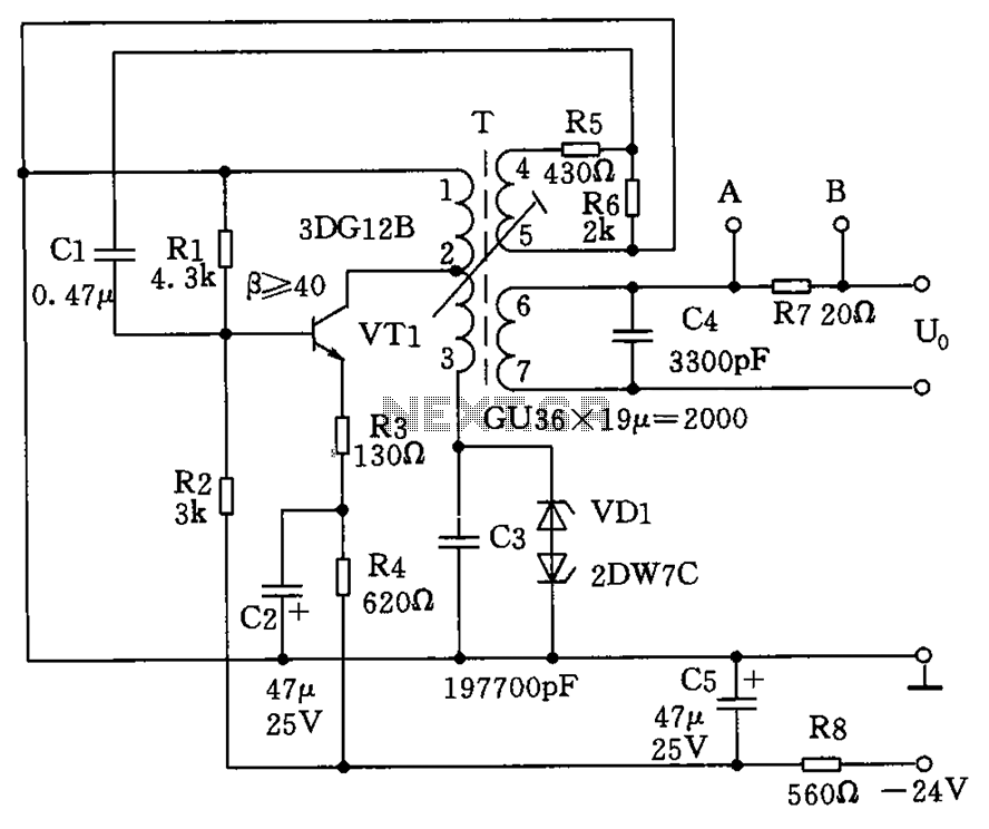
1.8kHz signal generator circuit
The circuit depicted in the figure allows for the selection of optimal operating conditions and a suitable allocation of the temperature coefficient for the resonant circuit components. The resonance occurs at both ends of the circuit. Additionally, the exchange regulator...
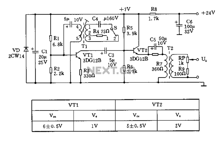
450 800Hz signal generator circuit diagram
The 450/800Hz oscillation circuit depicted in the figure utilizes transformer coupling. The frequency conversion is achieved by varying the inductance through a variable filter tap (T1). When the switch control signal (S) is set to position 1, the oscillator circuit...
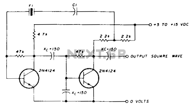
Low-frequency oscillator 10-150khz
A capacitor in series with the crystal may be utilized to adjust the oscillator output frequency. The value may range between 20 pF and 0.01 µF, or it may be a trimmer capacitor, and it will approximately equal the crystal...
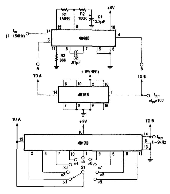
Low-Frequency Prescaler
For multiplying frequencies in the 1 to 150 Hz range, this circuit utilizes a 4046B phase-locked loop (PLL) and a 100 prescaler. The output from the voltage-controlled oscillator (VCO) is phase-locked to the low-frequency input. This configuration facilitates the use...
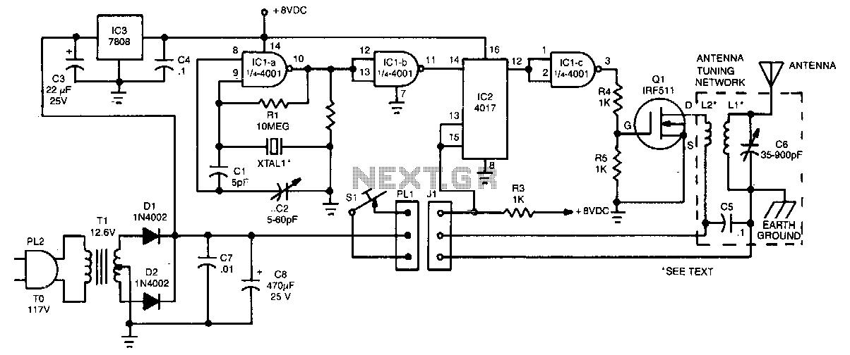
Low-frequency-transmitter
The crystal oscillator utilizes two sections of IC1, a 4001 quad 2-input NOR gate, representing a standard and reliable design. The oscillator generates a 1.85-MHz square-wave output that feeds into IC2, a 4017 divide-by-10 counter. The count enable and reset...
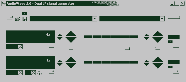
AudioWave 2.0
With AudioWave 2.0 your soundcard becomes a comfortable LF-signal-generator, which produces signals from 1Hz to 20 kHz with a resolution of 1 Hz. Phase shift between left and right channel is adjustable from 180° to +180° and an attenuator can...
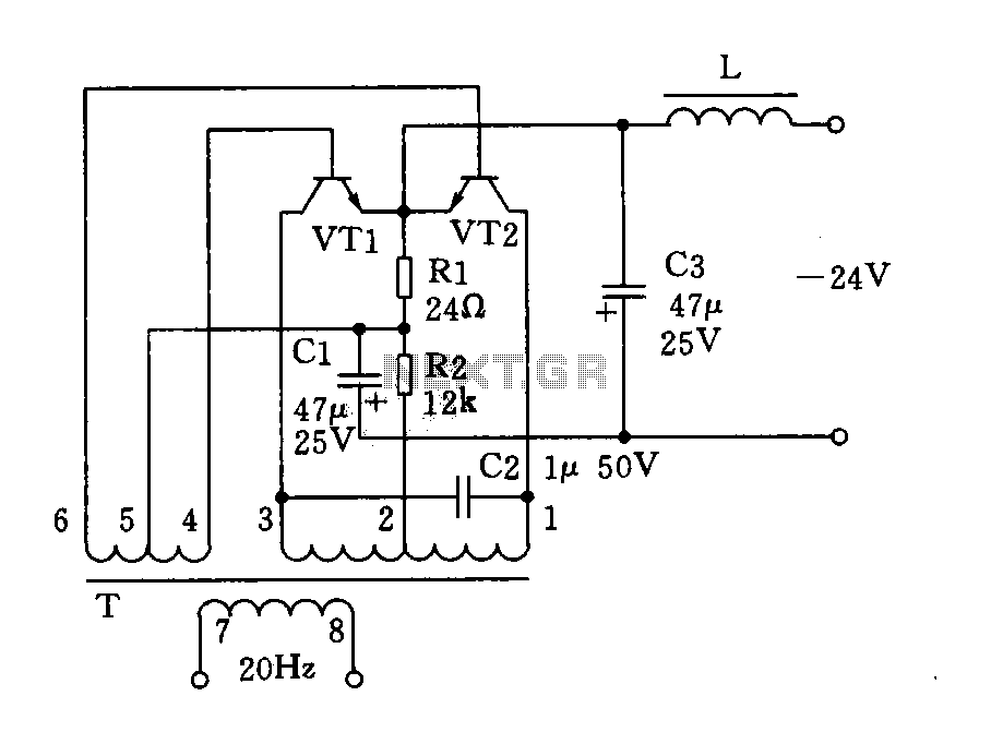
20Hz signal generator (phone-ringing) circuit diagram
The circuit described is a 20Hz signal generator suitable for telephone ringing systems, alarm systems, and various other electronic applications. It consists of a transformer (T) and two transistors (VT1 and VT2), forming a push-pull oscillator. The two transistors operate...

The Multi-purpose signal generator circuit
The multi-purpose signal generator circuit consists of integrated circuit oscillators and frequency dividers. It generates square waves ranging from high frequencies to sub-audio frequencies and also produces a frequency standard in the VHF range. The alternative oscillator section feeds the...
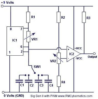
DIY Homemade Signal Generator with Pulse Width Modulation
Construct a signal generator using readily available components. It should produce a square wave with variable frequency and adjustable pulse width. This device can be utilized for various applications, including DC motor speed regulation, dimming of lamps or LEDs, transformer...