


Inverters form three-phase VCO
#inverters
#three-phase
#VCO
#ring oscillator
#Texas Instruments
#waveforms
#unbuffered
#U-type inverters
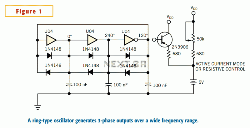
Description: The inspiration for the VCO in Figure 1 came from Texas Instruments application notes of years ago, detailing the use of unbuffered U-type inverters for use in ring oscillators. The application notes circuit consists of only the inverters. The circuit generates relatively squarish waveforms. Any ring oscillators operation depends on the fact that an odd number of inversions exists around the loop. More: Any odd number of inverters would work. The feedback is inverting, or negative. The feedback creates an initial bias equilibrium at the transition voltage for the gates. Loop gain greater than unity is a necessary condition for oscillation. Unbuff
The Voltage-Controlled Oscillator (VCO) described utilizes a configuration of unbuffered U-type inverters arranged in a ring oscillator format. This design is inspired by classic application notes from Texas Instruments, which highlight the effective use of these inverters in generating oscillatory signals.
In this circuit, an odd number of inverters is essential, as it ensures that the feedback loop introduces a negative or inverting feedback mechanism. This configuration is crucial for maintaining the oscillation since it allows the signal to propagate through the loop, creating a continuous oscillatory output. The generated waveforms are characterized as relatively squarish, which is typical for ring oscillator designs due to the sharp transitions between high and low states.
The operational principle of the ring oscillator hinges on the concept of loop gain. For the circuit to oscillate, the loop gain must exceed unity. This condition ensures that the feedback signal is strong enough to sustain oscillations. Moreover, the feedback mechanism establishes an initial bias equilibrium at the transition voltage of the inverter gates, allowing for stable operation.
The implementation of this VCO can vary based on the number of inverters used, as any odd number will suffice. Careful consideration must be given to the specific characteristics of the inverters employed, including their switching speeds and propagation delays, as these parameters will influence the frequency and stability of the oscillation.
Overall, the described circuit serves as a foundational design for various applications requiring oscillatory signals, including clock generation, signal modulation, and frequency synthesis. The simplicity of the configuration, coupled with its effectiveness, makes it a valuable reference for engineers and designers working in the field of electronics.The inspiration for the VCO in Figure 1 came from Texas Instruments application notes of years ago, detailing the use of unbuffered U-type inverters for use in ring oscillators. The application notes circuit consists of only the inverters. The circuit generates relatively squarish waveforms. Any ring oscillators operation depends on the fact that an odd number of inversions exists around the loop.
The Voltage-Controlled Oscillator (VCO) described utilizes a configuration of unbuffered U-type inverters arranged in a ring oscillator format. This design is inspired by classic application notes from Texas Instruments, which highlight the effective use of these inverters in generating oscillatory signals.
In this circuit, an odd number of inverters is essential, as it ensures that the feedback loop introduces a negative or inverting feedback mechanism. This configuration is crucial for maintaining the oscillation since it allows the signal to propagate through the loop, creating a continuous oscillatory output. The generated waveforms are characterized as relatively squarish, which is typical for ring oscillator designs due to the sharp transitions between high and low states.
The operational principle of the ring oscillator hinges on the concept of loop gain. For the circuit to oscillate, the loop gain must exceed unity. This condition ensures that the feedback signal is strong enough to sustain oscillations. Moreover, the feedback mechanism establishes an initial bias equilibrium at the transition voltage of the inverter gates, allowing for stable operation.
The implementation of this VCO can vary based on the number of inverters used, as any odd number will suffice. Careful consideration must be given to the specific characteristics of the inverters employed, including their switching speeds and propagation delays, as these parameters will influence the frequency and stability of the oscillation.
Overall, the described circuit serves as a foundational design for various applications requiring oscillatory signals, including clock generation, signal modulation, and frequency synthesis. The simplicity of the configuration, coupled with its effectiveness, makes it a valuable reference for engineers and designers working in the field of electronics.The inspiration for the VCO in Figure 1 came from Texas Instruments application notes of years ago, detailing the use of unbuffered U-type inverters for use in ring oscillators. The application notes circuit consists of only the inverters. The circuit generates relatively squarish waveforms. Any ring oscillators operation depends on the fact that an odd number of inversions exists around the loop.
Any odd number of inverters would work.The feedback is inverting, or negative. The feedback creates an initial bias equilibrium at the transition voltage for the gates. Loop gain greater than unity is a necessary condition for oscillation. Unbuff
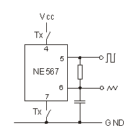
VCO with NE567
Who would like to build a sidetone oscillator with a minimum amount of parts should try the NE567 integrated circuit. The NE567 is a PLL circuit with an internal VCO for a operating frequency less than 500 kHz and it...
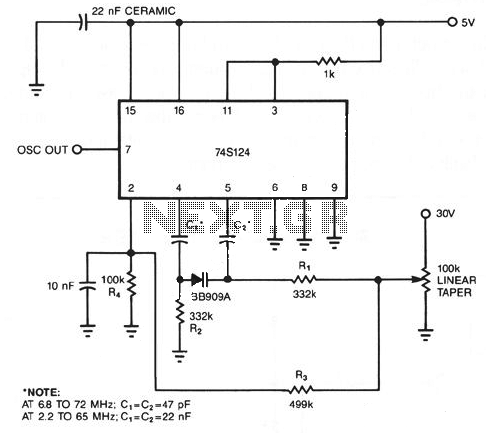
74S124 High Frequency VCO with Varactor
The following schematic diagram illustrates a conventional circuit modified to function as a voltage-controlled oscillator (VCO). By substituting the fixed capacitor with a variable capacitance diode (varactor), a 74S124 multivibrator can be transformed into a wide-band VCO. The high-speed logic...
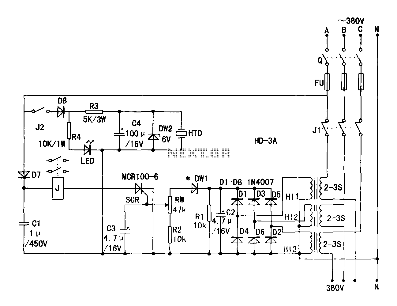
HD a 3A limit energy-saving three-phase power protection circuit
A current transformer H11-3 needs to be constructed. Select a transformer core with a minimum power rating of 2W for the first secondary winding. Use enameled wire with a diameter of 0.12 mm and wind approximately 1000 turns. The primary...
Asynchronous power wiring diagram
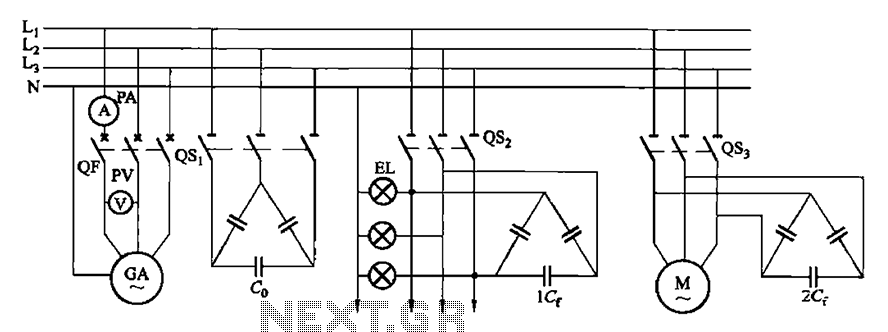
A three-phase squirrel cage induction motor is driven by a prime mover (such as diesel engines) and has asynchronous motor stator windings connected to the output end along with several capacitors for excitation power, enabling it to produce three-phase alternating...
Voltage Controlled Oscillator with Varactor
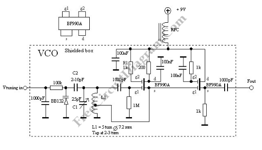
This is a Voltage Controlled Oscillator (VCO) circuit. This circuit is based on a Hartley oscillator. The frequency depends on the values of C1 and L1.
The Voltage Controlled Oscillator (VCO) circuit described operates using a Hartley oscillator configuration, which is...
Tracking Advances in VCO Technology
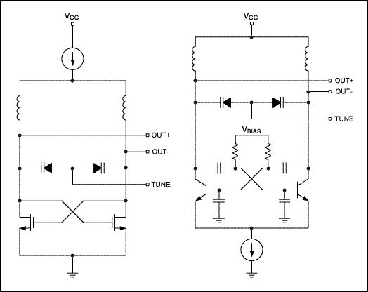
This document tracks the history of voltage-controlled oscillators (VCOs) since around 1910 and provides examples of VCO integration in RF integrated circuits (ICs).
Voltage-controlled oscillators (VCOs) are critical components in various electronic systems, particularly in radio frequency (RF) applications. A VCO...
Tremolo
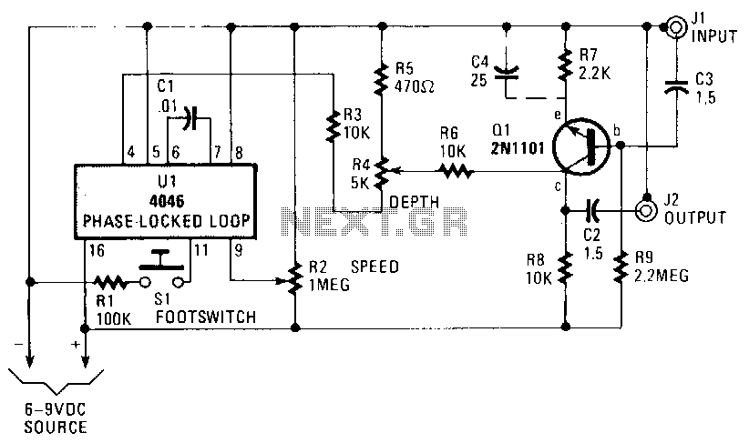
The voltage-controlled oscillator (VCO) of U1, part of a phase-locked loop, generates a low-frequency square-wave signal ranging from 5 Hz to 2500 Hz. The frequency is modulated by adjusting the voltage at pin 9 through resistor R2. The frequency threshold...
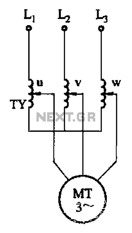
Three phase torque motor speed control circuit
The circuit depicted in Figure 3-176 illustrates an adjustment method that allows the motor to operate at equilibrium. The adjustment range is relatively wide; however, it necessitates a three-phase voltage regulator, which incurs higher input costs.
The circuit design in Figure...
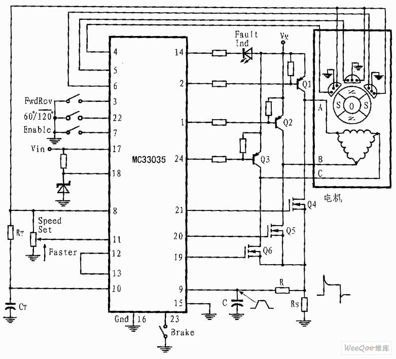
Three-phase and Six-step Motor Control Circuit of MC33035
The presented three-phase application circuit features a motor controller circuit connection diagram that operates using a full-wave six-step method. The power switch is a Darlington PNP type, while the lower power switch is an N-channel power MOSFET. Each device incorporates...