


Low phase noise voltage controlled oscillator circuit
#voltage controlled oscillator
#low phase noise
#VCO
#oscillator
#RF
#frequency control
#electronic circuits
#signal generation
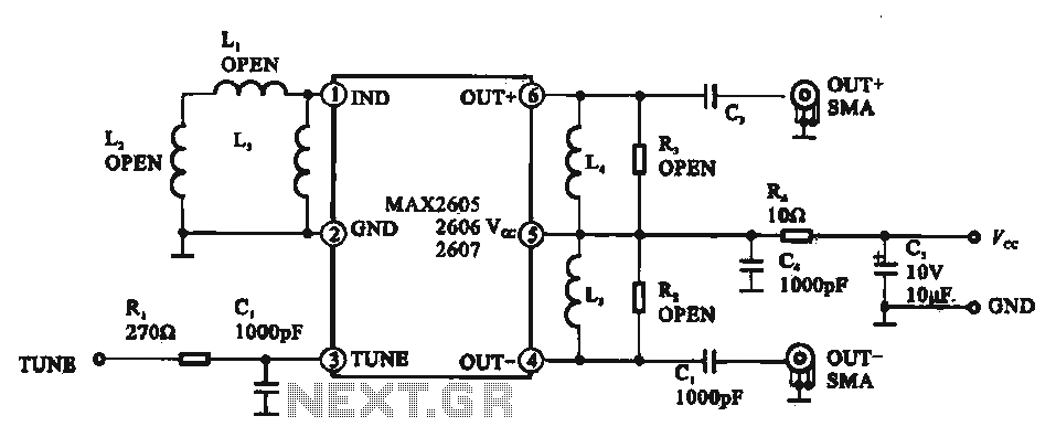
Description: A low phase noise voltage-controlled oscillator circuit is presented, specifically integrated within the MAX2605-2609 voltage-controlled oscillator series. The circuit features a tuning voltage control terminal, allowing for adjustable oscillation frequency through a DC voltage input. The output of the oscillator circuit provides both positive and negative polarity oscillation signals.
The MAX2605-2609 series of voltage-controlled oscillators (VCOs) are designed to deliver low phase noise performance, making them suitable for applications requiring high-frequency stability and precision. The circuit operates by utilizing a tuning voltage that adjusts the frequency of oscillation in response to external control signals. The tuning voltage is applied to a dedicated terminal on the integrated circuit, which modulates the frequency output based on the input voltage level.
This VCO circuit typically employs a feedback mechanism to maintain the desired frequency stability. The output stage can generate oscillation signals with both positive and negative polarities, which are essential for various applications in communication systems, frequency synthesis, and signal modulation.
The design of the circuit includes critical components such as inductors, capacitors, and resistors, which work in conjunction with the internal architecture of the MAX2605-2609 to optimize performance. The low phase noise characteristic is achieved through careful selection of these components and the implementation of a well-designed feedback loop that minimizes jitter and phase distortion.
Applications for this low phase noise VCO circuit include RF transmitters and receivers, local oscillators in phase-locked loops (PLLs), and other RF signal processing tasks where signal integrity and frequency accuracy are paramount. The ability to adjust the oscillation frequency via a DC voltage input allows for flexibility in tuning, making this circuit a valuable component in modern electronic systems.Low phase noise voltage controlled oscillator circuit a It shows a typical low phase noise voltage controlled oscillator circuit, which is integrated in MAX2605-2609 voltage controlled oscillator circuit. Feet tuning voltage control terminal, the oscillation frequency of the DC voltage adjustable end chip. feet and legs were positive and negative polarity of the oscillation signal output.
The MAX2605-2609 series of voltage-controlled oscillators (VCOs) are designed to deliver low phase noise performance, making them suitable for applications requiring high-frequency stability and precision. The circuit operates by utilizing a tuning voltage that adjusts the frequency of oscillation in response to external control signals. The tuning voltage is applied to a dedicated terminal on the integrated circuit, which modulates the frequency output based on the input voltage level.
This VCO circuit typically employs a feedback mechanism to maintain the desired frequency stability. The output stage can generate oscillation signals with both positive and negative polarities, which are essential for various applications in communication systems, frequency synthesis, and signal modulation.
The design of the circuit includes critical components such as inductors, capacitors, and resistors, which work in conjunction with the internal architecture of the MAX2605-2609 to optimize performance. The low phase noise characteristic is achieved through careful selection of these components and the implementation of a well-designed feedback loop that minimizes jitter and phase distortion.
Applications for this low phase noise VCO circuit include RF transmitters and receivers, local oscillators in phase-locked loops (PLLs), and other RF signal processing tasks where signal integrity and frequency accuracy are paramount. The ability to adjust the oscillation frequency via a DC voltage input allows for flexibility in tuning, making this circuit a valuable component in modern electronic systems.Low phase noise voltage controlled oscillator circuit a It shows a typical low phase noise voltage controlled oscillator circuit, which is integrated in MAX2605-2609 voltage controlled oscillator circuit. Feet tuning voltage control terminal, the oscillation frequency of the DC voltage adjustable end chip. feet and legs were positive and negative polarity of the oscillation signal output.
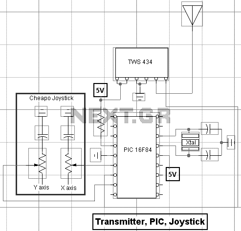
Building an RF Remote Control System For Robotics Control
With a handful of inexpensive components, a little creativity, and the power of PicBasic, you can build some pretty outstanding robotics creations as Rob Arnold proves with his Ruf-Bot project. RF remote control is just way too cool not to...
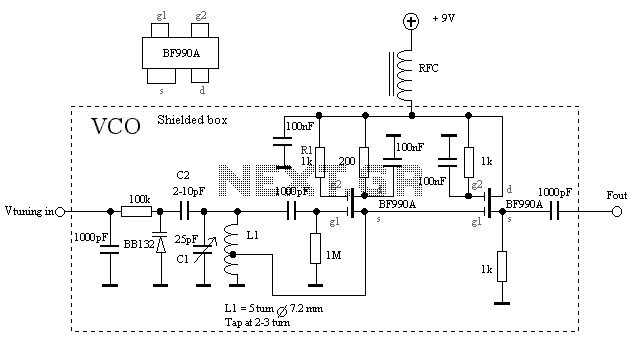
Voltage Controlled Oscillator with BF990A
The VCO is based on a Hartley oscillator. The frequency is determined by L1 and capacitor C1. The tuning voltage will change the capacitance in the varactor BB132 which will change the oscillation frequency. The value of capacitor C2 will...
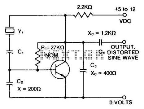
150 To 30000Khz Oscillator
A capacitor in series with the crystal can be utilized to adjust the output frequency of the oscillator. The value can range between 20 pF and 0.01 µF, or it can be a trimmer capacitor. The values are approximate and...
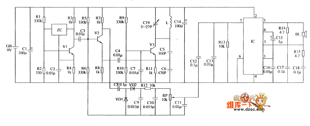
Metal detector circuit diagram 1
The metal detector circuit includes a fixed frequency oscillator, mixer, detector, detection oscillator, and power amplifier circuit. The fixed frequency oscillator circuit is composed of a ceramic filter (ZC), transistor (V1), resistors (R1 to R4), capacitor (C2), and other components....
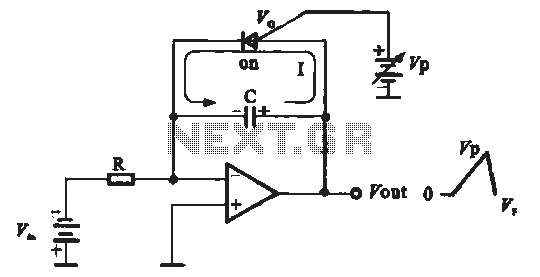
Sawtooth voltage controlled oscillator
A sawtooth voltage-controlled oscillator operates by first generating a negative potential maximum at the output of the comparator. This output is then fed to the inverting input terminal through resistor R1, which is part of the relaxation oscillator. The relaxation...
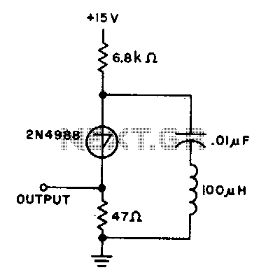
10Khz oscillator
The capacitor charges until the switching voltage is reached. When the switch (SUS) is activated, the inductor causes the current to oscillate. When the current through the switch drops below the holding current, the device turns off, and the cycle...
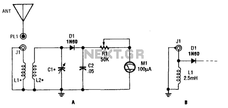
Tuned Rf Wavemeter
L1 and L2 form a tuned transformer with an optimum turns ratio of approximately 1:3. L2 and C1 are used to tune to the desired frequency. The frequency range can extend from 10 kHz to over 200 MHz, depending on...
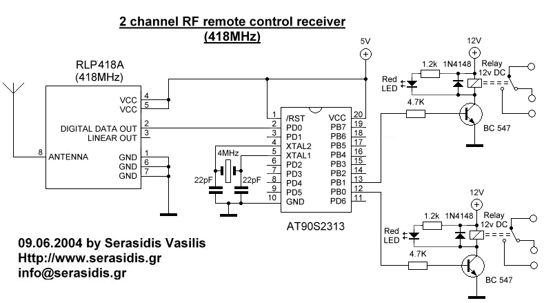
2 channel RF remote control
The basic small-range remote controls are Infrared and RF (Radio Frequency). One of the weaknesses of Infrared is that the signal cannot pass through walls. Therefore, to control a garage door, an RF remote control is necessary. The circuit (transmitter...
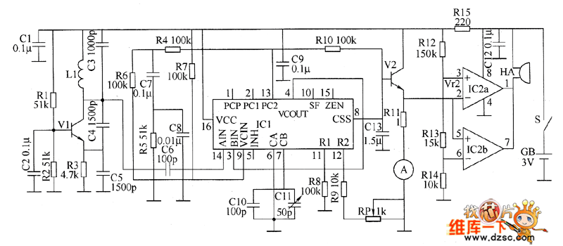
Metal detector circuit diagram 8
The metal detector circuit consists of a probe oscillator, a PLL (phase-locked loop) circuit, and an audio alarm circuit. The probe oscillator includes a detection coil (L), transistor (V1), and several resistors (R1 to R3) and capacitors (C1 to C5)....