Multilayer capacitor doubles as varactor
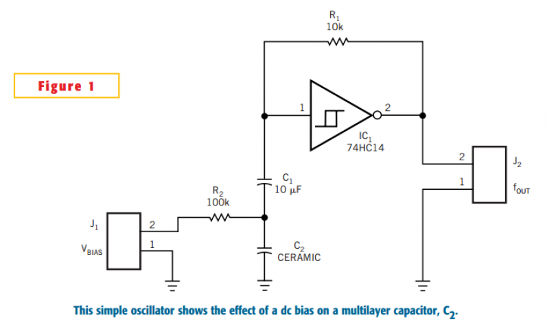
The circuit is a simple oscillator using a Schmitt-trigger inverter. The frequency is a function of R1, C1, and C2. C2 is the ceramic capacitor with voltage-dependent capacitance. Using the value of C1, the frequency can be shifted independently of C2.
This design uses a stable-foil-type capacitor for C1 to avoid bias-voltage-dependent effects in the measured results. If necessary, the temperature coefficient of the capacitor can be compensated with a combination of NTC, PTC, and metal-film resistors for R1. For measurements, this design uses a simple metal-film resistor. The capacitance change with temperature is normally less than 10% from 10 to 35°C for Z5U and Y5V and much lower for X5R.
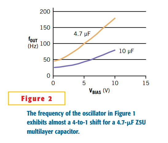
Figure 2 shows the measured voltage-versus-frequency graphs with different values and types for C2. For Figure 2, C1=10 µF; the orange curve represents a 4.7-µF, 10V, Z5U multilayer capacitor, and the purple curve represents a 10-µF, 10V, Z5U multilayer capacitor.
The VCO circuit described operates on the principle of varying frequency based on the control voltage applied to the capacitor C2, which is a ceramic capacitor known for its voltage-dependent capacitance characteristics. The oscillator is based on a Schmitt-trigger inverter, which provides hysteresis and stability to the circuit, ensuring a clean square wave output. The resistors R1 and the capacitors C1 and C2 form an RC timing network that determines the frequency of oscillation.
The choice of C1 as a stable-foil-type capacitor is critical, as it mitigates the influence of temperature and bias voltage variations on the circuit's performance. The design allows for independent frequency adjustment by varying C1 while maintaining the voltage-dependent characteristics of C2, which is essential for the VCO's operation.
Compensation for temperature variations can be achieved through the use of thermistors (NTC and PTC) in conjunction with precision metal-film resistors, ensuring that the oscillator remains stable across a range of operating conditions. The performance of the circuit can be evaluated through voltage versus frequency plots, which illustrate the effects of different capacitor types and values on the frequency output of the VCO, providing valuable insights into the design's effectiveness and reliability.The circuit is also an inexpensive VCO (voltage-controlled oscillator) with only five components. Many types of ceramic capacitors for surface-mount placement are on the market. The parts become continually smaller because of space problems on the board, and the capacitance values continually increase to compete with more expensive tantalum-electrolytic units. Unfortunately, capacitors with X5R, Z5U, or Y5V dielectrics have some undesirable properties.
They exhibit voltage-dependent capacitance values. The idea behind the circuit in Figure 1 is to check the influence of a dc bias voltage on the frequency of a simple oscillator. The net result is a low-frequency VCO with a relatively large voltage-gain figure, which depends largely on the type of capacitor you use.
The circuit is a simple oscillator using a Schmitt-trigger inverter.
The frequency is a function of R1, C1, and C2. C2 is the ceramic capacitor with voltage-dependent capacitance. Using the value of C1, you can shift the frequency independently of C2.
This design uses a stable-foil-type capacitor for C1 to avoid bias-voltage-dependent effects in the measured results. If necessary, you can compensate the temperature coefficient of the capacitor with a combination of NTC, PTC, and metal-film resistors for R1.
For measurements, this design uses a simple metal-film resistor. The capacitance change with temperature is normally less than 10% from 10 to 35°C for Z5U and Y5V and much lower for X5R.
Figure 2 shows the measured voltage-versus-frequency graphs with different values and types for C2. For Figure 2, C1=10 µF; the orange curve represents a 4.7-µF, 10V, Z5U multilayer capacitor, and the purple curve represents a 10-µF, 10V, Z5U multilayer capacitor.