


Sawtooth generator circuit
#sawtooth generator
#NBTV
#test signal
#video path
#sync pulses
#linearity
#1volt output
#31 line sync
#dynamic range
#video signal
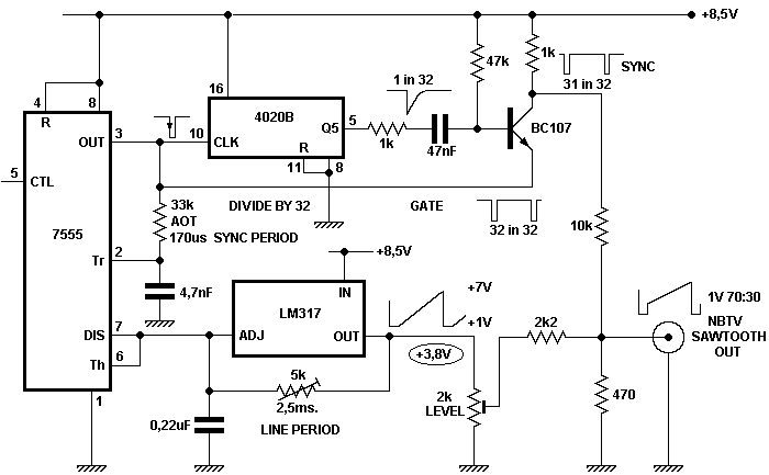
Description: To achieve optimal performance from an NBTV signal, it is crucial to utilize the complete dynamic range of the signal without any crushing at the black level or peak white. To evaluate the linearity of a video path, it is common practice to use either a staircase or sawtooth test signal. The circuit outlined is a standalone NBTV sawtooth generator that adheres to the standard output level of 1 volt and includes 31 line sync pulses. More specifically, the 7555 timer and LM317 regulator create a linear sawtooth generator. Two timing capacitors are utilized: one determines the active line time, which can be adjusted using a potentiometer, while the other sets the duration of the line sync. This circuit is distinctive in that the LM317 serves dual purposes. It functions as a constant current generator to linearly charge the 0.22 µF capacitor and also provides a very low output impedance. The 4020 counter is employed as a divide-by-32, receiving input from line pulses. A grounded base transistor differentiates the falling edge from Q5 of the 4020, gating out one sync pulse out of 32, with the output from the gate being non-inverting. The remaining 31 sync pulses are combined with an attenuated sawtooth to generate a standard 70%-30% 1 V NBTV signal, which is delivered at a nominal impedance of 470 ohms.
The described NBTV sawtooth generator circuit is a sophisticated design that effectively produces a linear sawtooth waveform essential for generating test signals in narrow-band television systems. The choice of components, such as the 7555 timer and LM317 voltage regulator, ensures stability and precision in the output signal. The 7555 timer functions as the heart of the sawtooth generator, where its timing characteristics are carefully adjusted to create a linear ramp voltage. The use of two timing capacitors allows for fine-tuning of the active line time and line sync duration, ensuring that the output signal conforms to the required specifications for NBTV.
The LM317 regulator's role as a constant current source is critical for achieving a linear charge on the timing capacitor, which is vital for maintaining the integrity of the sawtooth waveform. Its low output impedance further enhances the performance by minimizing signal distortion, which is particularly important for video signals where fidelity is paramount.
The 4020 binary counter's implementation as a divide-by-32 mechanism allows for precise generation of the required line sync pulses, which are essential for synchronizing the video signal. The grounded base transistor configuration effectively differentiates the signal, ensuring that only the necessary sync pulses are produced. This selective gating process contributes to a clean and well-defined output signal.
Finally, the mixing of the attenuated sawtooth waveform with the 31 sync pulses results in a standardized NBTV signal characterized by a 70%-30% duty cycle at 1 V output. This configuration is particularly suited for applications in narrow-band television, where signal integrity and adherence to standards are critical. The output impedance of 470 ohms is also a standard value that facilitates compatibility with various video equipment, ensuring that the generator can be easily integrated into existing systems.To get the best from an NBTV signal it is important to use the full dynamic range of the signal with no crushing at black level or peak white. To check the linearity of a video path it is usual to use either a staircase or sawtooth test signal.
The circuit described is a free standing NBTV sawtooth generator conforming to the standard of 1volt output level and complete with 31 line sync pulses. The 7555 timer and LM317 regulator form a linear sawtooth generator. Two timing capacitors are employed, one setting the active line time which may be trimmed by the pot, the second sets the line sync duration. The circuit is un-usual in that the LM317 performs two roles. It acts as constant current genera-tor to linearly charge the 0. 22 mF capacitor, and also provides a very low output impedance. The 4020 counter is used as a divide-by-32 fed from line pulses. The grounded base transistor differentiates the falling edge from Q5 of the 4020 and gates out one sync pulse in 32, the output from the gate being non-inverting.
The remaining 31 sync pulses are mixed with an attenuated sawtooth to form a standard 70%-30% 1 V NBTV signal and delivered at a nominal 470 © impedance.
The described NBTV sawtooth generator circuit is a sophisticated design that effectively produces a linear sawtooth waveform essential for generating test signals in narrow-band television systems. The choice of components, such as the 7555 timer and LM317 voltage regulator, ensures stability and precision in the output signal. The 7555 timer functions as the heart of the sawtooth generator, where its timing characteristics are carefully adjusted to create a linear ramp voltage. The use of two timing capacitors allows for fine-tuning of the active line time and line sync duration, ensuring that the output signal conforms to the required specifications for NBTV.
The LM317 regulator's role as a constant current source is critical for achieving a linear charge on the timing capacitor, which is vital for maintaining the integrity of the sawtooth waveform. Its low output impedance further enhances the performance by minimizing signal distortion, which is particularly important for video signals where fidelity is paramount.
The 4020 binary counter's implementation as a divide-by-32 mechanism allows for precise generation of the required line sync pulses, which are essential for synchronizing the video signal. The grounded base transistor configuration effectively differentiates the signal, ensuring that only the necessary sync pulses are produced. This selective gating process contributes to a clean and well-defined output signal.
Finally, the mixing of the attenuated sawtooth waveform with the 31 sync pulses results in a standardized NBTV signal characterized by a 70%-30% duty cycle at 1 V output. This configuration is particularly suited for applications in narrow-band television, where signal integrity and adherence to standards are critical. The output impedance of 470 ohms is also a standard value that facilitates compatibility with various video equipment, ensuring that the generator can be easily integrated into existing systems.To get the best from an NBTV signal it is important to use the full dynamic range of the signal with no crushing at black level or peak white. To check the linearity of a video path it is usual to use either a staircase or sawtooth test signal.
The circuit described is a free standing NBTV sawtooth generator conforming to the standard of 1volt output level and complete with 31 line sync pulses. The 7555 timer and LM317 regulator form a linear sawtooth generator. Two timing capacitors are employed, one setting the active line time which may be trimmed by the pot, the second sets the line sync duration. The circuit is un-usual in that the LM317 performs two roles. It acts as constant current genera-tor to linearly charge the 0. 22 mF capacitor, and also provides a very low output impedance. The 4020 counter is used as a divide-by-32 fed from line pulses. The grounded base transistor differentiates the falling edge from Q5 of the 4020 and gates out one sync pulse in 32, the output from the gate being non-inverting.
The remaining 31 sync pulses are mixed with an attenuated sawtooth to form a standard 70%-30% 1 V NBTV signal and delivered at a nominal 470 © impedance.
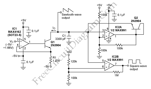
High Performance Sawtooth Generator
This is a simple sawtooth generator circuit. The advantages of this circuit include low cost and the ability to produce an auxiliary square wave at the same frequency. This circuit can be utilized to sweep the frequency of another generator....
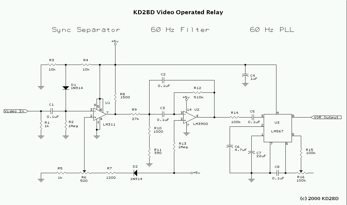
Video Operated Relay
Many Video Operated Relay (VOR) circuits have been published in recent years for use in connection with ATV repeater controllers or automatic videotape logging systems. Unfortunately, many of these circuits fail to properly detect certain video signals depending on their...
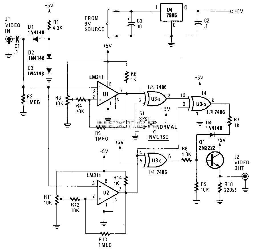
Picture-fixer-inverter
The circuit accepts a video signal, separates the sync pulses, inverts the video, and integrates new video with the existing sync pulses. The video signal is input through J1 and processed by a clamping circuit comprising C1, D1, D2, D3,...
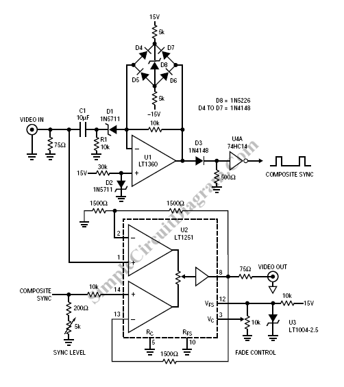
Video Fader Circuit
Fading a video signal cannot be achieved merely by attenuating the composite signal, as the synchronization signal may fall below an unacceptable level.
Fading a video signal involves a careful adjustment of both the luminance and chrominance components while maintaining...
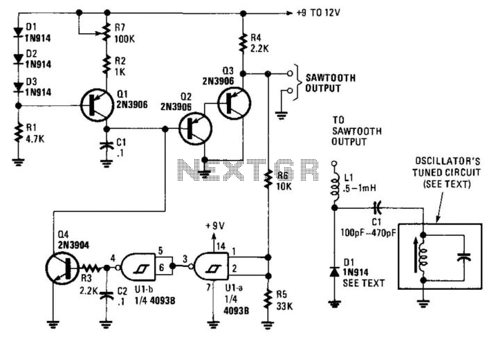
Sawtooth Generator For Sweep Generators
This circuit generates a linear sawtooth waveform with a frequency range from 30 Hz to 3,000 Hz. Q1 acts as a constant-current source that charges capacitor C1 until the output level at the emitter of Q3 triggers operational amplifiers U1A...
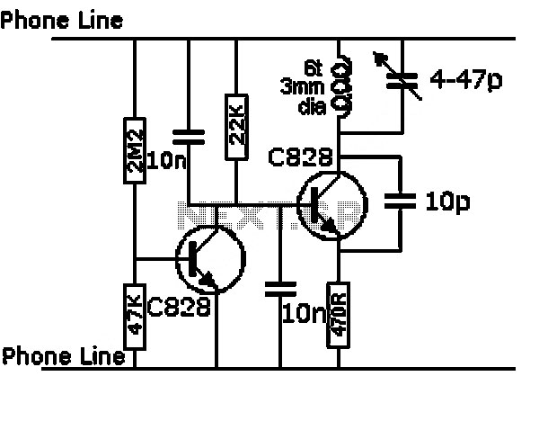
high performance sawtooth generator
This is a design for a sawtooth generator circuit. The advantage of this circuit is its low cost and the capability to produce an auxiliary square wave at the same frequency. This circuit can be utilized to sweep the frequency...
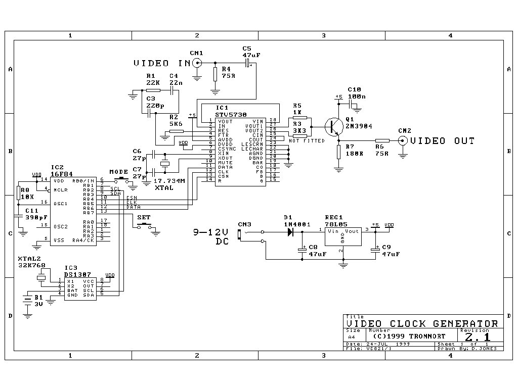
Video Clock and Message Generator
This circuit allows for the superimposition of a title and/or the time and date on an incoming video signal, which is particularly useful when editing video tapes. With the advent of affordable CCD camera modules, setting up a personal video...
Video Fader Circuit
Fading a video signal cannot be achieved merely by attenuating the composite signal, as the synchronization signal may fall below an unacceptable level.
Fading a video signal involves a careful adjustment of both the luminance and chrominance components while maintaining...

TV as display terminal interface circuit diagram
The interface circuit is placed between the computer's standard video signal output terminal and the television. It amplifies the standard 1V (Peak-to-Peak) video signal to 3V (Peak-to-Peak). The negative feedback circuit consists of transistors T1 and T2, providing a wide...