


Strobe-tone burst generator
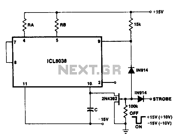
Description: With a dual supply voltage, the external capacitor on pin 10 can be connected to ground to stop the oscillation of the 8038. The circuit employs a FET switch and a diode, which are combined with an input strobe signal to ensure that the output consistently begins on the same slope.
The 8038 function generator is a versatile and highly stable oscillator capable of producing sine, square, triangular, and sawtooth waveforms. In applications where precise timing and waveform generation are critical, the ability to control the oscillation is essential. The dual supply voltage configuration allows for flexible operation across various circuit designs.
Pin 10 of the 8038 is connected to an external capacitor, which plays a crucial role in determining the frequency and stability of the oscillation. By connecting this capacitor to ground, the oscillation can be halted effectively, providing a means to reset or stop the output waveform when needed. This feature is particularly useful in applications requiring synchronization or precise timing control.
The implementation of a FET switch in conjunction with a diode enhances the circuit's functionality. The FET switch can be controlled by an input strobe signal, which allows for dynamic control of the output waveform. The diode serves to protect the circuit from reverse polarity and ensures that the strobe signal only influences the FET switch when intended. This configuration allows the output to consistently start from the same slope, ensuring repeatability and reliability in waveform generation.
In summary, this circuit design leverages the capabilities of the 8038 function generator, utilizing an external capacitor for oscillation control and a FET switch with a diode for precise output management. Such design considerations are critical in applications ranging from signal processing to timing circuits, where accuracy and stability are paramount.With a dual supply voltage, the external capacitor on pin 10 can be shorted to ground to halt the 8038 oscillation The circuit uses a FET switch and diode ANDed with an input strobe signal to allow the output to always start on the same slope.
The 8038 function generator is a versatile and highly stable oscillator capable of producing sine, square, triangular, and sawtooth waveforms. In applications where precise timing and waveform generation are critical, the ability to control the oscillation is essential. The dual supply voltage configuration allows for flexible operation across various circuit designs.
Pin 10 of the 8038 is connected to an external capacitor, which plays a crucial role in determining the frequency and stability of the oscillation. By connecting this capacitor to ground, the oscillation can be halted effectively, providing a means to reset or stop the output waveform when needed. This feature is particularly useful in applications requiring synchronization or precise timing control.
The implementation of a FET switch in conjunction with a diode enhances the circuit's functionality. The FET switch can be controlled by an input strobe signal, which allows for dynamic control of the output waveform. The diode serves to protect the circuit from reverse polarity and ensures that the strobe signal only influences the FET switch when intended. This configuration allows the output to consistently start from the same slope, ensuring repeatability and reliability in waveform generation.
In summary, this circuit design leverages the capabilities of the 8038 function generator, utilizing an external capacitor for oscillation control and a FET switch with a diode for precise output management. Such design considerations are critical in applications ranging from signal processing to timing circuits, where accuracy and stability are paramount.With a dual supply voltage, the external capacitor on pin 10 can be shorted to ground to halt the 8038 oscillation The circuit uses a FET switch and diode ANDed with an input strobe signal to allow the output to always start on the same slope.
ELF MONITOR
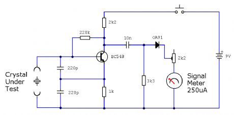
The capacitor instrument is not intended for measuring the capacitance of capacitors; rather, it is designed to identify whether a capacitor is functional or defective, as well as to detect short circuits or open circuits. This functionality provides reliable quality...
From the same period and vehicle route map
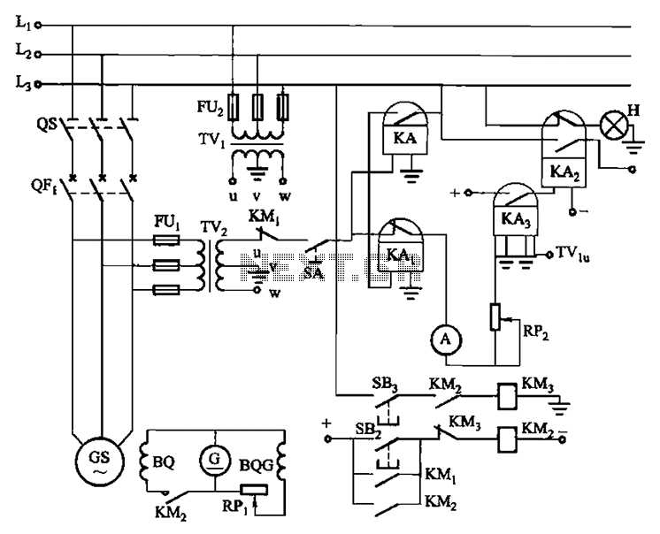
Vehicles from the same period utilize a generator without excitation, which means there is no voltage generator bus, only residual voltage (approximately ten volts). This makes operation relatively simple. It is necessary to wait until the generator speed (frequency) rises...
Help me Understand this Circuit Schematic
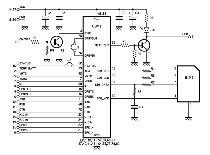
The roles of capacitors C1, C4, and C5 in a circuit may not be immediately clear. Capacitors on the power rail help to smooth out the signal by reducing current ripple, which can be observed using an oscilloscope. Resistors R6...
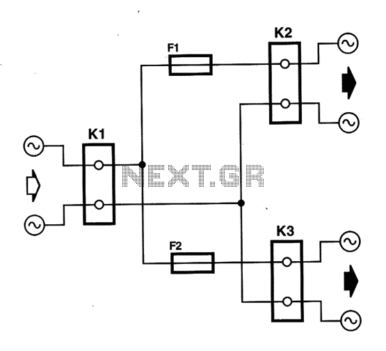
Dual supply for audio amplifiers
Most amplifiers operate at acoustic frequencies, sometimes requiring two or even three transformers instead of a single power transformer. This approach is more prevalent in high-end amplifiers, where enthusiasts often prioritize high fidelity over cost. In these setups, the primary...
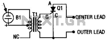
Photo Strobe Slave Trigger Circuit
The photo strobe slave trigger circuit utilizes a solar cell and a silicon-controlled rectifier (SCR) to activate any strobe light when triggered by a master strobe. The small solar cell generates a minimal voltage when illuminated.
The photo strobe slave trigger...
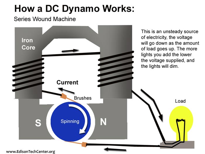
Generators
A mechanical power source is required, such as a turbine powered by falling water, a wind turbine, a gas turbine, or a steam turbine. A shaft from one of these devices is connected to a generator to produce power. Dynamos...
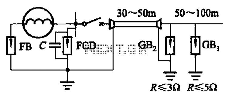
300 to 1500kW straight with a generator of Lightning
300 to 1500 kW direct distribution lightning generator designed for single capacities ranging from 300 kW to 1500 kW.
The lightning generator operates within a power range of 300 kW to 1500 kW, providing a direct distribution system that facilitates the...
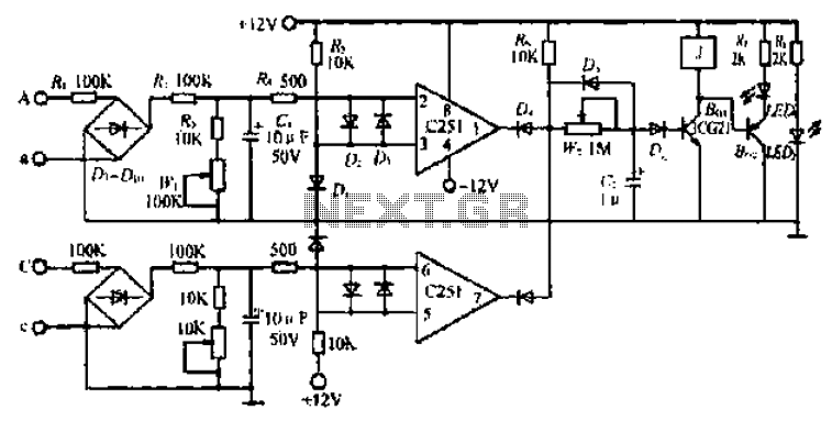
A small generator and network control circuit
Circle i represents a two-phase grid connection line for an AC technology turbine shed, which consists of two lines. A voltage is generated between Ri through a Buck converter, with components R1 and R3 dividing the output. The sampled level...
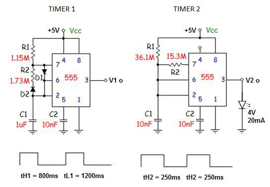
Need help with strobe circuit
Unfortunately, there is no breadboard available for testing; however, modifications can be made to the PCB. The 1K potentiometer has been removed until the strobe functionality can be established.
The circuit in question appears to involve a strobe light mechanism, which...