



Pulse-Generator & Signal-Tracer
This simple circuit generates narrow pulses at about 700-800Hz frequency. The pulses, containing harmonics up to the MHz region, can be injected into audio or r...
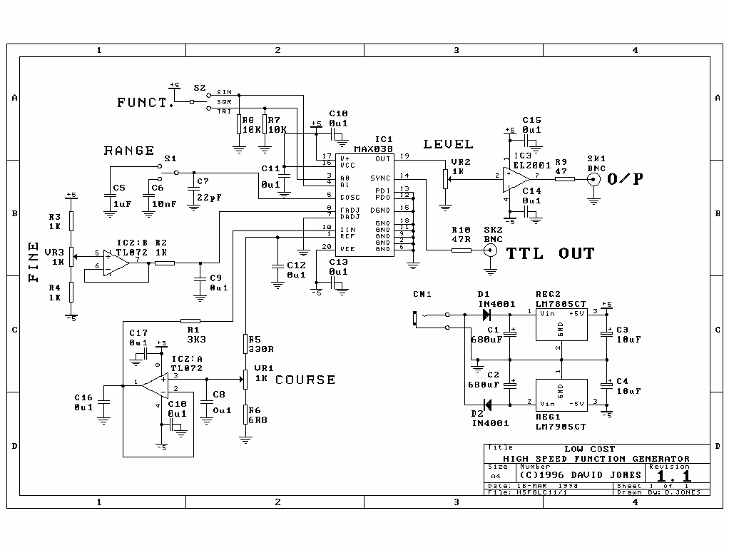
20MHz High Speed Function Generator
The High Speed Function Generator was published in the professional electronics section of the Aug 1996 issue of Electronics Australia, and has proven to be ext...
20MHz High Speed Function Generator
The High Speed Function Generator was published in the professional electronics section of the Aug 1996 issue of Electronics Australia, and has proven to be ext...
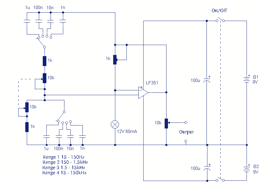
Sine wave oscillator II
In this circuit the gain is provided by a FET type op-amp. I have used an LF351, which may be hard to obtain, but the TL071CN or TL081CN may be used and have a ...
Sine wave oscillator II
In this circuit the gain is provided by a FET type op-amp. I have used an LF351, which may be hard to obtain, but the TL071CN or TL081CN may be used and have a ...

1KHz Sine wave Generator
This circuit generates a good 1KHz sinewave adopting the inverted Wien bridge configuration (C1-R3 & C2-R4). It features a variable output, low distortion a...
1KHz Sine wave Generator
This circuit generates a good 1KHz sinewave adopting the inverted Wien bridge configuration (C1-R3 & C2-R4). It features a variable output, low distortion a...
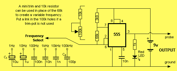
SQUARE WAVE OSCILLATOR
This project is a piece of test equipment. It`s a square wave oscillator with 6 selectable frequencies from 1Hz to 100kHz, incrementing in decade values. It`s m...
SQUARE WAVE OSCILLATOR
This project is a piece of test equipment. It`s a square wave oscillator with 6 selectable frequencies from 1Hz to 100kHz, incrementing in decade values. It`s m...

Simple Square wave Generator
This simple circuit generates a good and stable 1V peak-to-peak square wave at 100Hz, 1KHz and 10KHz using a single 1.5V cell as power supply. An useful feature...
Simple Square wave Generator
This simple circuit generates a good and stable 1V peak-to-peak square wave at 100Hz, 1KHz and 10KHz using a single 1.5V cell as power supply. An useful feature...
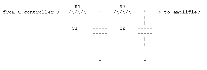
Rounding Off a square wave
To "round" your square wave, you need to integrate it twice; once to produce a triangular wave, and a second time to produce a parabolic waveform. (A parabolic ...
Rounding Off a square wave
To "round" your square wave, you need to integrate it twice; once to produce a triangular wave, and a second time to produce a parabolic waveform. (A parabolic ...
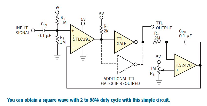
Convert periodic waveforms to square waves
Converting periodic waveforms to square waves is an integral part of extracting a clock signal from data, creating waveform generators, and making timing-pulse ...
Convert periodic waveforms to square waves
Converting periodic waveforms to square waves is an integral part of extracting a clock signal from data, creating waveform generators, and making timing-pulse ...
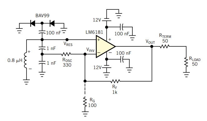
RF oscillator uses current-feedback op amp
A current-feedback amplifier is a well-known component with many uses. Its basic block diagram shows that its input stage is a voltage followerin practice, a sy...
RF oscillator uses current-feedback op amp
A current-feedback amplifier is a well-known component with many uses. Its basic block diagram shows that its input stage is a voltage followerin practice, a sy...
Hartley
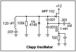
A Hartley oscillator is shown at the right. It uses most of the same components as the Clapp oscillator. A capacitor is necessary to block the gate bias voltage...
Hartley
A Hartley oscillator is shown at the right. It uses most of the same components as the Clapp oscillator. A capacitor is necessary to block the gate bias voltage...
BFO Circuit
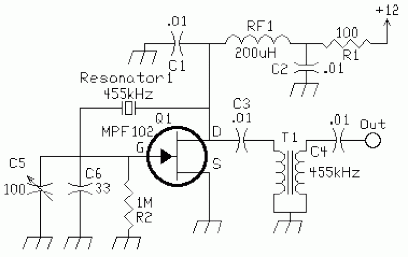
This circuit was used to stop all the BFO drift. The circuit is extremely stable. Turn the receiver off, and then on at any time and temperature, the BFO freque...