

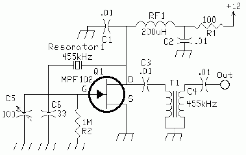

BFO Circuit
This circuit was used to stop all the BFO drift. The circuit is extremely stable. Turn the receiver off, and then on at any time and temperature, the BFO freque...
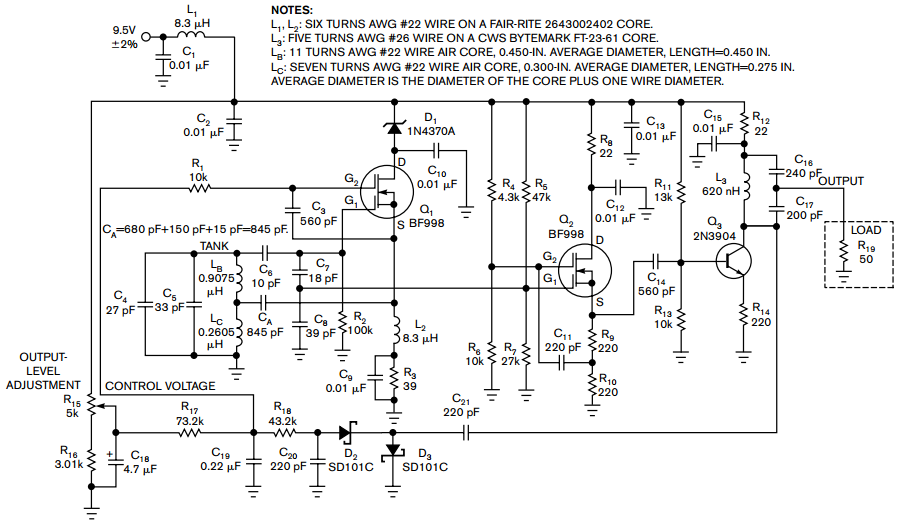
Hartley oscillator requires no coupled inductors
Examine a traditional Hartley oscillator circuit, and you`ll note its trademark: a tapped inductor that determines the frequency of oscillation and provides osc...
Hartley oscillator requires no coupled inductors
Examine a traditional Hartley oscillator circuit, and you`ll note its trademark: a tapped inductor that determines the frequency of oscillation and provides osc...
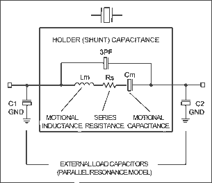
Specifying Quartz Crystals
This article explains the specifications and characteristics of crystals and crystal oscillators, and aids in specifying crystals and working with crystal vendo...
Specifying Quartz Crystals
This article explains the specifications and characteristics of crystals and crystal oscillators, and aids in specifying crystals and working with crystal vendo...
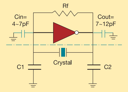
Pierce-gate oscillator crystal load calculation
The crystal used in the topology of Figure 1 can be either a fundamental AT-CUT or BT-CUT. A BT-CUT crystal has poor frequency stability over temperature compar...
Pierce-gate oscillator crystal load calculation
The crystal used in the topology of Figure 1 can be either a fundamental AT-CUT or BT-CUT. A BT-CUT crystal has poor frequency stability over temperature compar...
Pierce Crystal Oscillator Design
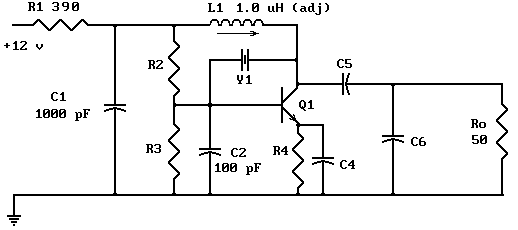
The Pierce oscillator shown above is essentially a common emitter amplifier with a tuned circuit for a collector load and a quartz crystal as a feedback element...
Pierce Crystal Oscillator Design
The Pierce oscillator shown above is essentially a common emitter amplifier with a tuned circuit for a collector load and a quartz crystal as a feedback element...
HCMOS Crystal Oscillators
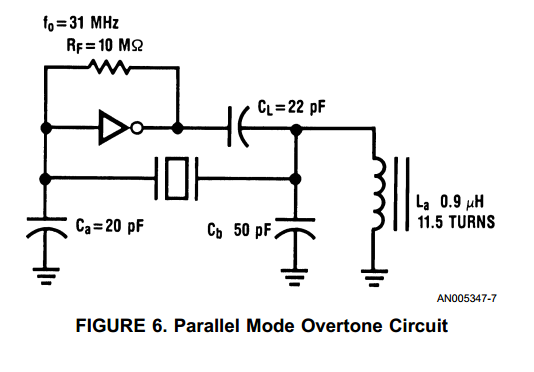
With the advent of high speed HCMOS circuits, it is possible to build systems with clock rates of greater than 30 MHz. The familiar gate oscillator circuits use...
HCMOS Crystal Oscillators
With the advent of high speed HCMOS circuits, it is possible to build systems with clock rates of greater than 30 MHz. The familiar gate oscillator circuits use...
Crystal Oscillator II
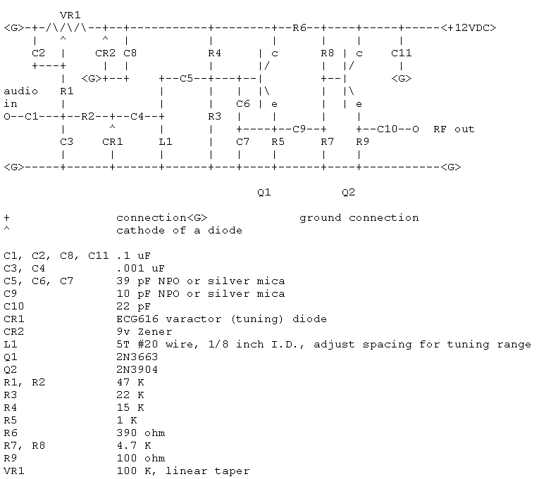
The world is full of xtal oscillators twiddled by digital designers lacking in the analog design knowledge necessary. Just look at all the PC real time clocks t...
Crystal Oscillator II
The world is full of xtal oscillators twiddled by digital designers lacking in the analog design knowledge necessary. Just look at all the PC real time clocks t...
A Colpitts VCO for Wideband (0.952.15 GHz)
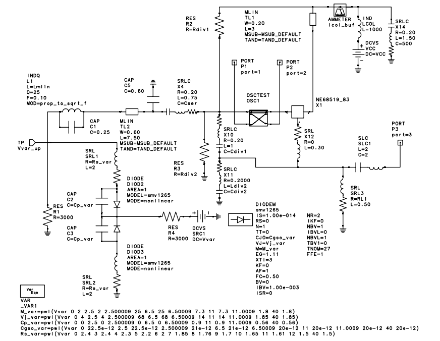
Modern set-top DBS TV tuners require high performance, broadband voltage control oscillator (VCO) designs at a competitive cost.To meet these goals, design engi...
A Colpitts VCO for Wideband (0.952.15 GHz)
Modern set-top DBS TV tuners require high performance, broadband voltage control oscillator (VCO) designs at a competitive cost.To meet these goals, design engi...
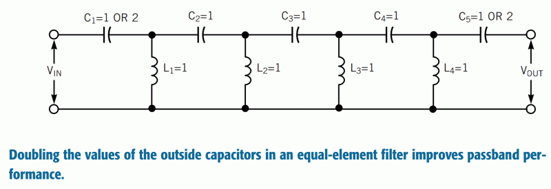
Highpass filters use modified equal-element design
Using a modified equal-element design for a lumped-circuit lowpass filter has several advantages over the well-known equal-element design (Reference 1 and Refer...
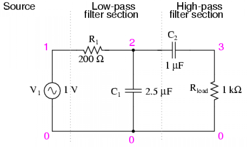
Band-pass filters
There are applications where a particular band, or spread, or frequencies need to be filtered from a wider range of mixed signals. Filter circuits can be design...
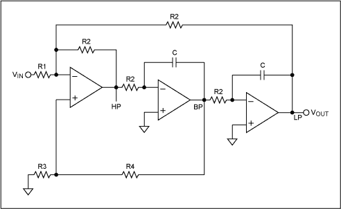
Cascade bandpass filters for higher Q
Switched-capacitor filters that are preset for a given bandwidth sometimes do not deliver the bandwidth or Q an application requires. By inverting the clock bet...
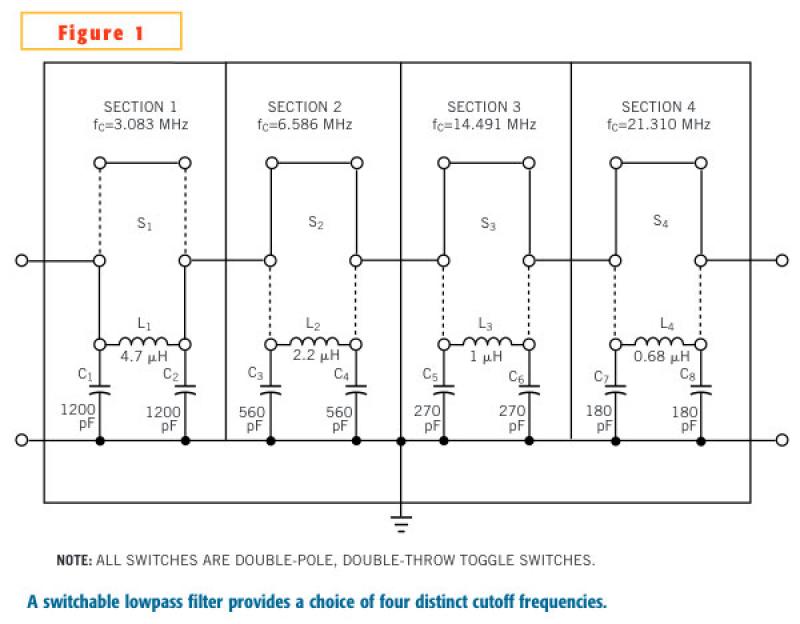
Adjustable filter provides lowpass response
In an adjustable lowpass filter, each filter section uses commonly available components (Figure 1). This example uses filter-section cutoff frequencies for stan...