


Power frequency noise filter PC822 schematic
#noise filter
#double-T filter
#50Hz
#60Hz
#signal amplification
#sensor
#power supply noise
#filter circuit
#frequency filter
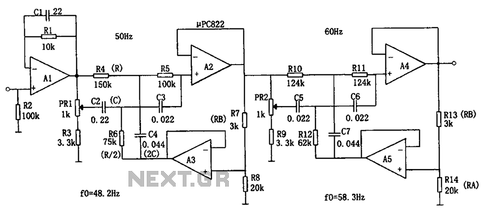
Description: The circuit depicted in the figure is a frequency power supply noise filter circuit, specifically a double-T filter. It is designed to amplify weak signals, such as those from sensors, while filtering out mixed 50Hz (or 60Hz) power supply frequency noise. Using only an RC element to construct this filter typically results in a low Q value and a broadband attenuation characteristic. However, the incorporation of operational amplifiers with positive feedback enhances the Q value. The Q value can be expressed as Q = Q/(1 + K), where K is defined as RA/(RA + RB). By adjusting the coefficient K, the Q value can be increased. The resonant frequency of the circuit is given by f0 = 1/(2πRC), with the positive feedback elements represented as R/2 and 2C. To account for the effects of capacitive decentralization, the resonant frequency is set lower, and the potentiometers PR1 and PR2 are used to adjust the frequency to either 50Hz or 60Hz. When a 50Hz (or 60Hz) sinusoidal voltage is applied, the filter can be adjusted via PR to minimize the output voltage. This filter is capable of handling input power supply noise that is not a sine wave, which may introduce high-frequency components. The low-pass filter can effectively filter out higher harmonics, such as the 3rd, 5th, and 7th odd harmonics present in AC power.
The double-T filter circuit is an effective solution for reducing power supply noise in electronic systems, particularly in applications where precision is critical, such as sensor signal processing. The design utilizes operational amplifiers to improve the Q factor, thus enhancing the selectivity of the filter. The ability to adjust the resonant frequency using potentiometers allows for fine-tuning based on the specific frequency of the noise present in the power supply.
In practical applications, the circuit can be integrated into various electronic devices to mitigate interference from the 50Hz or 60Hz power lines. The design's reliance on both resistive and capacitive components ensures that it can effectively handle a range of frequencies, while the feedback mechanism permits dynamic adjustments to the filter characteristics based on the operating environment.
When implementing this filter, consideration should be given to the layout and component selection to minimize parasitic capacitance and inductance, which could adversely affect performance. Additionally, the choice of operational amplifiers should align with the desired frequency response and gain characteristics to achieve optimal filtering results. Overall, this circuit serves as a robust solution for enhancing signal integrity in the presence of power supply noise. As shown in FIG frequency power supply noise filter circuit. The circuit is a double-T filter, can be used to amplify (such as sensors) weak signal, to mixed 50Hz (or 60Hz) pow er supply frequency noise will be filtered out. If using only the RC element composed of such filter, the Q value is generally low, and the attenuation characteristic having broadband characteristics. Using op amps and add positive feedback can improve the Q value. Let Q value at this time is Q, then Q Q/(1 a K), where, K RA/(RA + RB). Changing the coefficient K can make Q value increases. The resonant frequency of the circuit is fo 1/2 RC, positive feedback element of R/2 and 2C. Taking into account the characteristics of using a capacitive decentralization, the resonant frequency to be set lower, then the potentiometer PR1 and PR2 to adjust the frequency to 50Hz (or 60Hz).
When adjusting the input 50Hz (or 60Hz) sinusoidal voltage, filter it through PR adjust the output voltage to a minimum. With this filter, if the input power supply noise is not a sine wave, there will be a high-frequency component by the filter.
AC power is generally higher harmonics 3,5,7 and other odd harmonics can be filtered by low-pass filter access to these harmonics.
The double-T filter circuit is an effective solution for reducing power supply noise in electronic systems, particularly in applications where precision is critical, such as sensor signal processing. The design utilizes operational amplifiers to improve the Q factor, thus enhancing the selectivity of the filter. The ability to adjust the resonant frequency using potentiometers allows for fine-tuning based on the specific frequency of the noise present in the power supply.
In practical applications, the circuit can be integrated into various electronic devices to mitigate interference from the 50Hz or 60Hz power lines. The design's reliance on both resistive and capacitive components ensures that it can effectively handle a range of frequencies, while the feedback mechanism permits dynamic adjustments to the filter characteristics based on the operating environment.
When implementing this filter, consideration should be given to the layout and component selection to minimize parasitic capacitance and inductance, which could adversely affect performance. Additionally, the choice of operational amplifiers should align with the desired frequency response and gain characteristics to achieve optimal filtering results. Overall, this circuit serves as a robust solution for enhancing signal integrity in the presence of power supply noise. As shown in FIG frequency power supply noise filter circuit. The circuit is a double-T filter, can be used to amplify (such as sensors) weak signal, to mixed 50Hz (or 60Hz) pow er supply frequency noise will be filtered out. If using only the RC element composed of such filter, the Q value is generally low, and the attenuation characteristic having broadband characteristics. Using op amps and add positive feedback can improve the Q value. Let Q value at this time is Q, then Q Q/(1 a K), where, K RA/(RA + RB). Changing the coefficient K can make Q value increases. The resonant frequency of the circuit is fo 1/2 RC, positive feedback element of R/2 and 2C. Taking into account the characteristics of using a capacitive decentralization, the resonant frequency to be set lower, then the potentiometer PR1 and PR2 to adjust the frequency to 50Hz (or 60Hz).
When adjusting the input 50Hz (or 60Hz) sinusoidal voltage, filter it through PR adjust the output voltage to a minimum. With this filter, if the input power supply noise is not a sine wave, there will be a high-frequency component by the filter.
AC power is generally higher harmonics 3,5,7 and other odd harmonics can be filtered by low-pass filter access to these harmonics.
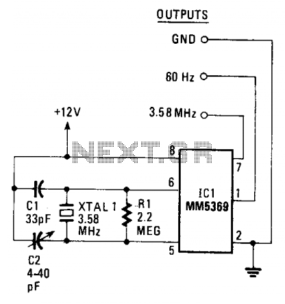
60Hz pulse generator
The circuit generates a clean, stable square wave and operates within a voltage range of 6 to 15 volts. The integrated circuit (IC) and color-burst crystal utilized are commonly found in television receivers. The output frequency of 3.58 MHz serves...
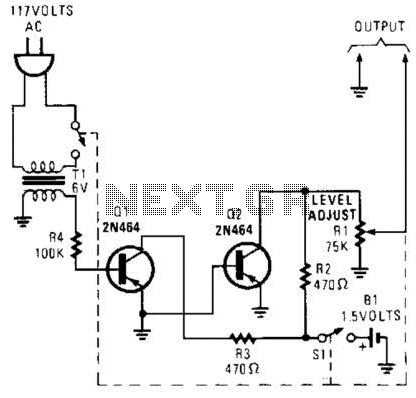
60Hz Square-Wave Generator Circuit
This generator circuit utilizes an overdriven amplifier to generate a 60 Hz square wave from the 60 Hz AC line. The circuit is suitable for line-operated applications as a clock source.
The generator circuit operates by leveraging an overdriven amplifier configuration,...
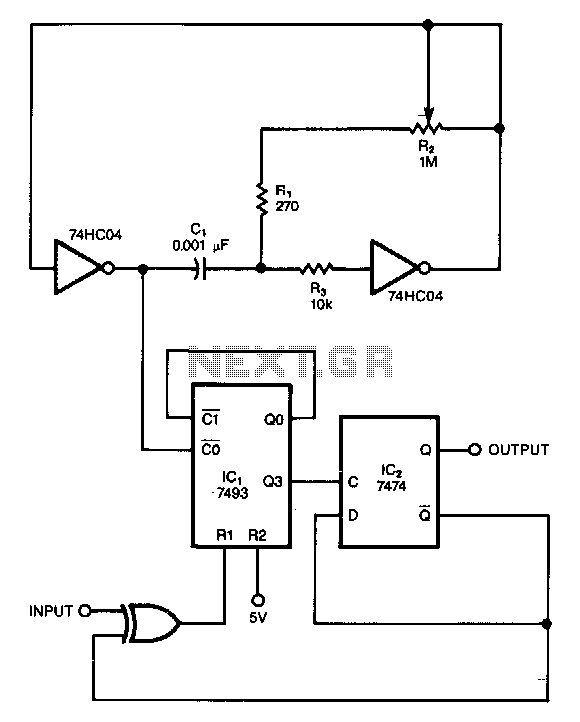
Noisy-signals-filter
This circuit filters noise, such as glitches and contact bounce, from digital signals. It can be easily adjusted for a wide range of noise frequencies. The circuit's output changes state only if the input differs from the output long enough...
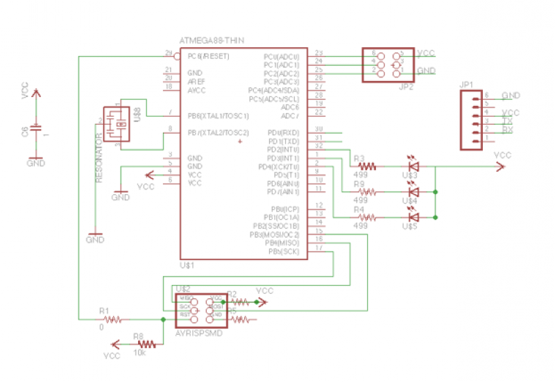
Add a sensor to a board and measure something with it
This week's plan is to build a device that warns of the potential for a knockdown, which is the process by which an over-canvassed ship is laid over on her beam-ends. The risk of sinking is high during this event,...
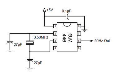
50hz accurate oscillator circuit
The ELM446 is an 8-pin digital divider integrated circuit that generates both 50Hz and 1Hz outputs from a common 3.58MHz NTSC colorburst crystal. The designer needs to supply only the crystal and two suitable loading capacitors, along with a properly...
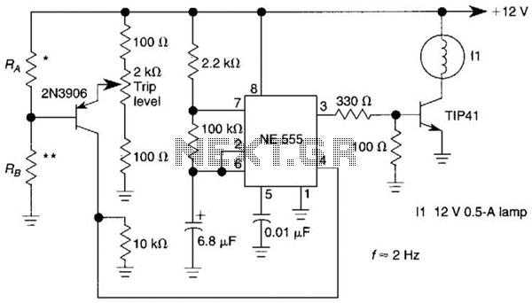
Sensor-Activated Relay Pulser Circuit
A sensor activates transistor Q1 to turn on the low-frequency 555 oscillator, which generates pulses to control LAMP II. The sensor may respond to variations in light or temperature. Either resistor RA or RB can function as the sensor, depending...
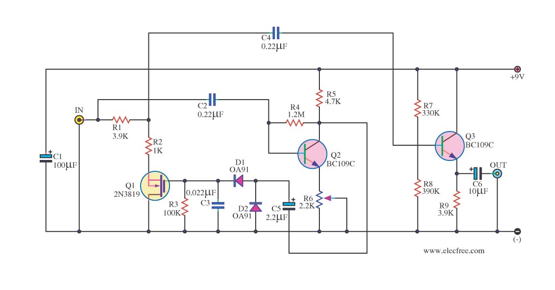
Audio noise filter circuits
In audio systems, noise signals are generally undesirable, and efforts are often made to eliminate them. Transistors can be utilized effectively for this purpose due to their availability and low noise characteristics. The following circuit serves as a Noise Filter...
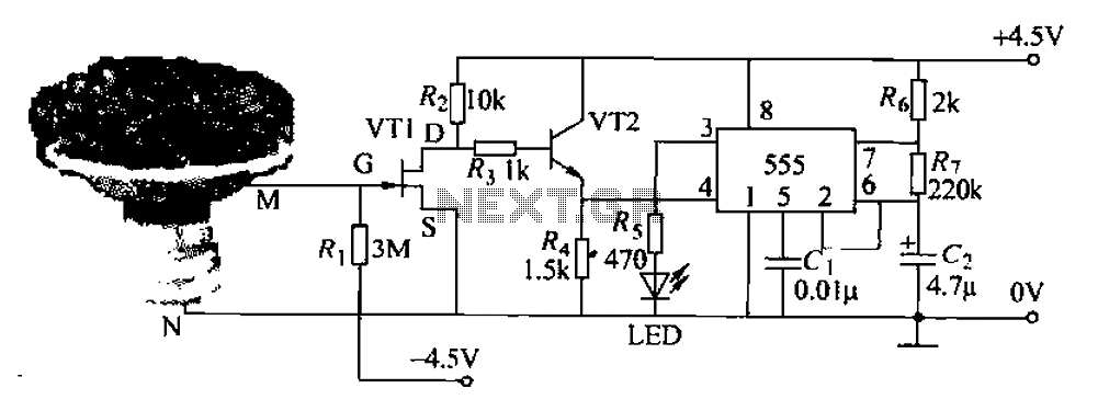
Pots water alarm circuit
The flowers in pots require watering, as relying solely on the observation of moist soil surfaces can be unreliable. To address this issue, a flower watering indicator has been developed. This circuit includes a field effect transistor (VT1), a second...
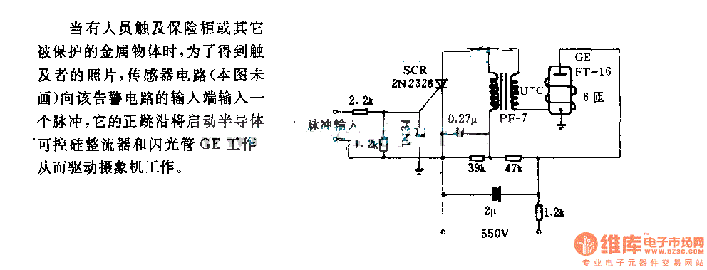
The alarm circuit diagram for safety box and other metal objects
When an individual touches the safety box or other protected metal objects, the sensor circuit generates a pulse to the alarm circuit. The positive edge of this pulse activates the semiconductor and thyristor flash GE, subsequently triggering the camera to...