


Single-supply-fault-monitor
#voltage monitor
#single supply
#over-voltage
#under-voltage
#hysteresis
#trip points
#fault detection
#power management
#circuit protection
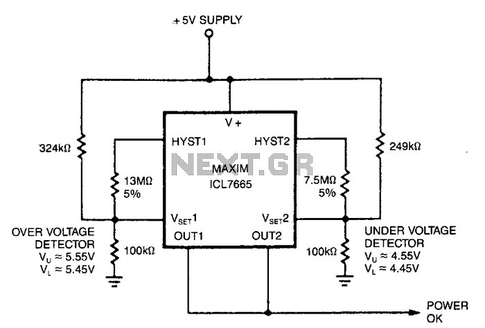
Description: This circuit illustrates a standard over/under-voltage fault monitor designed for a single power supply. The upper trip points, which control OUT 1, are set at 5.5 V with a hysteresis of 100 mV (Wu = 5.55 V, L = 5.45 V). The lower trip points, which control OUT 2, are centered at 4.5 V, also with a hysteresis of 100 mV. OUT 1 and OUT 2 are interconnected in a wired OR configuration to produce a power OK signal.
The over/under-voltage fault monitor circuit is essential for ensuring that the voltage levels remain within specified limits to protect sensitive electronic components. The upper trip point for OUT 1 is configured to activate when the supply voltage exceeds 5.55 V, while it deactivates when the voltage falls below 5.45 V. This hysteresis prevents rapid toggling of the output due to minor voltage fluctuations, which is crucial for stable operation.
Similarly, the lower trip point for OUT 2 activates when the supply voltage drops below 4.5 V and deactivates when the voltage rises above this threshold, also incorporating a hysteresis of 100 mV. The wired OR configuration of OUT 1 and OUT 2 allows for a single power OK signal to be generated. This signal indicates that the supply voltage is within the acceptable range, providing a simple yet effective means of monitoring the power supply status.
In practical applications, this circuit can be implemented using operational amplifiers or comparators configured to sense the voltage levels. The output signals can be used to trigger alarms, enable or disable power to other circuits, or provide feedback for microcontroller inputs. This design is particularly advantageous in power management systems, battery-operated devices, and various electronic applications where voltage regulation is critical.This circuit shows a typical over/under-voltage fault monitor for a single supply. The upper trip points, controlling OUT 1, are centered on 5.5 V with 100 mY of hysteresis Wu = 5.55 V, "L = 5.45 V); and the lower trip points, controlling OUT 2, are centered on 4.5 V, also with 100 mV of hysteresis. OUT 1 and OUT 2 are connected together in a wired OR configuration to generate a power OK signal.
The over/under-voltage fault monitor circuit is essential for ensuring that the voltage levels remain within specified limits to protect sensitive electronic components. The upper trip point for OUT 1 is configured to activate when the supply voltage exceeds 5.55 V, while it deactivates when the voltage falls below 5.45 V. This hysteresis prevents rapid toggling of the output due to minor voltage fluctuations, which is crucial for stable operation.
Similarly, the lower trip point for OUT 2 activates when the supply voltage drops below 4.5 V and deactivates when the voltage rises above this threshold, also incorporating a hysteresis of 100 mV. The wired OR configuration of OUT 1 and OUT 2 allows for a single power OK signal to be generated. This signal indicates that the supply voltage is within the acceptable range, providing a simple yet effective means of monitoring the power supply status.
In practical applications, this circuit can be implemented using operational amplifiers or comparators configured to sense the voltage levels. The output signals can be used to trigger alarms, enable or disable power to other circuits, or provide feedback for microcontroller inputs. This design is particularly advantageous in power management systems, battery-operated devices, and various electronic applications where voltage regulation is critical.This circuit shows a typical over/under-voltage fault monitor for a single supply. The upper trip points, controlling OUT 1, are centered on 5.5 V with 100 mY of hysteresis Wu = 5.55 V, "L = 5.45 V); and the lower trip points, controlling OUT 2, are centered on 4.5 V, also with 100 mV of hysteresis. OUT 1 and OUT 2 are connected together in a wired OR configuration to generate a power OK signal.
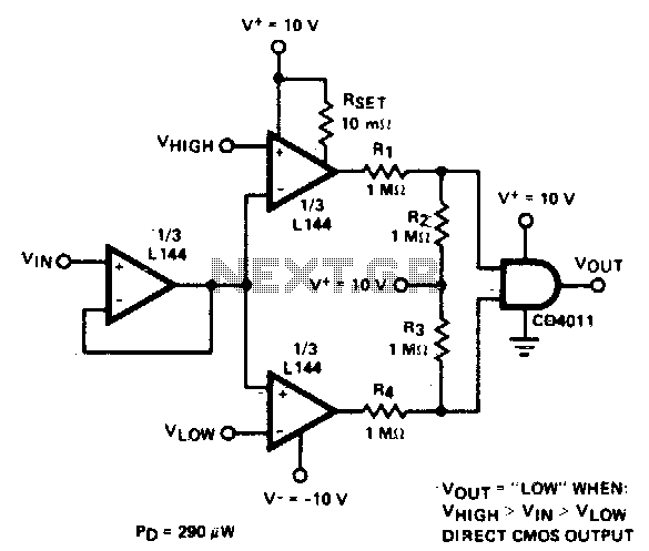
Double-ended limit detector
The detector employs three sections of an L144 and a CMOS NAND gate to create a low-power voltage monitor. The 1 MΩ resistors R1, R2, R3, and R4 convert the bipolar ±10 V swing of the operational amplifiers to a...
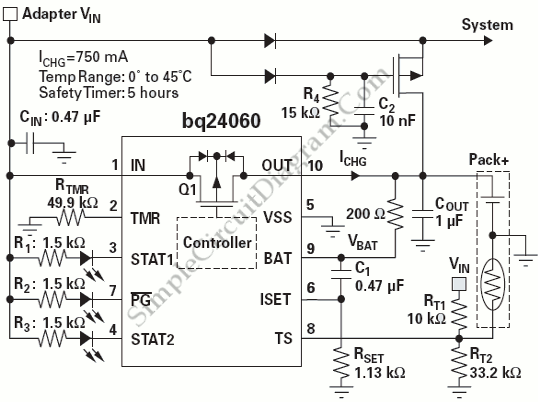
Power Path Management Battery Charger
Powering the system is required by many applications while charging the battery simultaneously. Interaction between the system and charger may result in a...
Power management in electronic systems is critical, particularly in applications that necessitate simultaneous operation and battery charging. This...
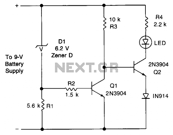
Voltage monitor circuit
This circuit provides an early warning for battery discharge. A Zener diode (D1) is selected to indicate when the voltage falls below 9 V. If the supply voltage drops below 7 V, D1 will stop conducting, which will cause transistor...
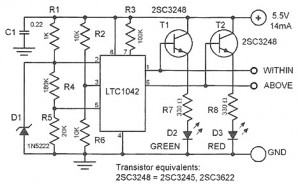
5 volt ttl voltage monitor
This device is designed to control a supply voltage of +5 V. It provides information signals at TTL levels, accompanied by an LED display that indicates whether the voltage is within the nominal value or deviates from it. The device...
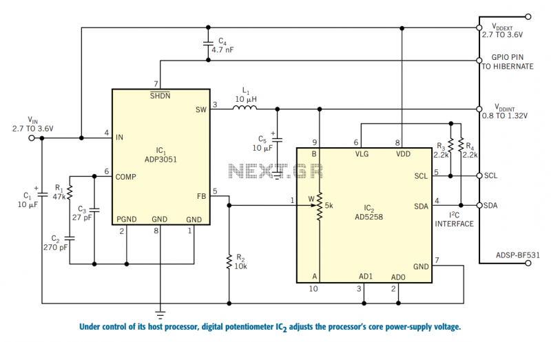
Control a processor`s power supply in real time
In battery-powered applications in which power management is key, a microprocessor may adjust its core voltage corresponding to an increase or a decrease in clock speed, allowing full processing power when necessary but not wasting excess power when idle. The...
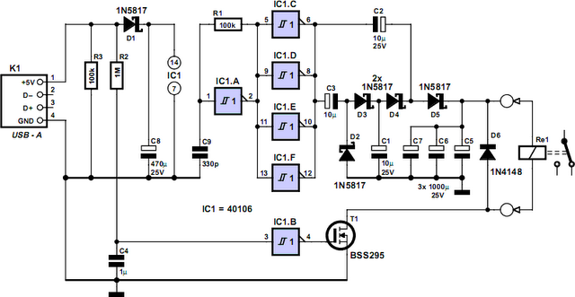
Computer Off Switch
How often does it happen that a user shuts down Windows and then forgets to turn off the computer? This circuit automates that process. After Windows is shut down, a click occurs a second later, disconnecting the PC from the...
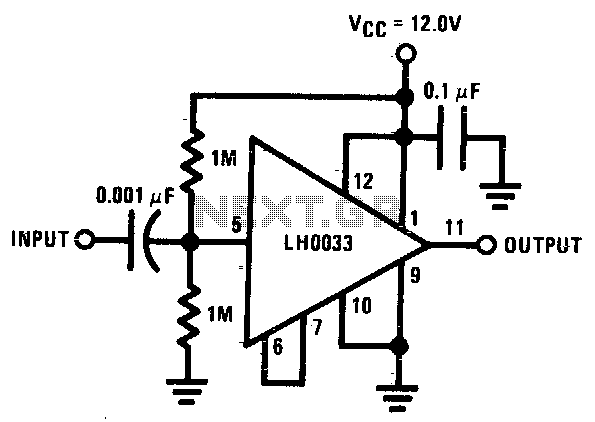
Single supply AC buffer amplifier
The input is DC biased to the mid-operating point and is AC coupled. Its input impedance is approximately 500K ohms at low frequencies. For DC loads referenced to ground, the quiescent current is increased by the load current set at...
How to extend the battery life of your microcontroller based design
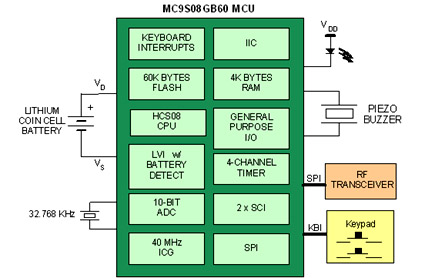
Battery-powered devices, such as electric toothbrushes, shavers, cell phones, PDAs, MP3 players, and remote controls, are integral to daily life. Consequently, power management has become a critical consideration for embedded designers. Microcontrollers (MCUs) provide various methods for managing power requirements...
Over-under-voltage-monitor
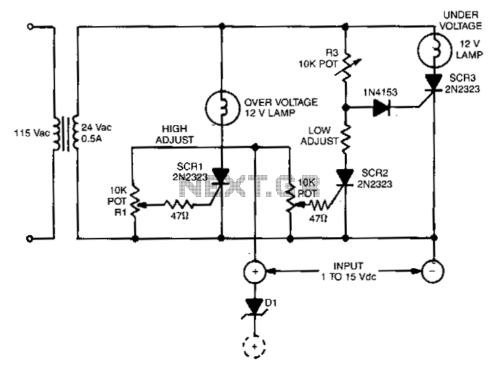
This circuit is capable of monitoring any voltage potential ranging from 1 to 15 V. It features two lamps that indicate any undesirable voltage variations. The voltage differential between the lamp turning on and turning off is approximately 0.2 V...