


Transformerless Power Supply Circuit-Ouputs 5 Volt DC
#transformerless
#5V DC
#low cost
#low current
#LED power
#simple circuit
#power supply diagram
#schematics
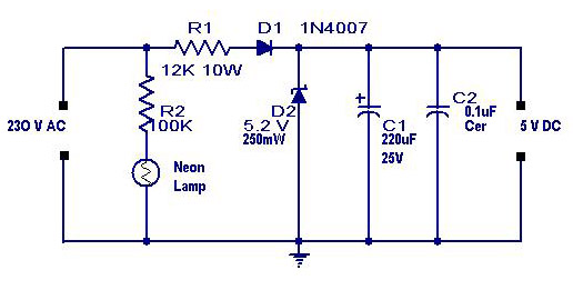
Description: A simple transformerless power supply circuit with a diagram and schematics that provides a 5 volts DC output. This is a low-cost, low-current power supply circuit suitable for simple applications such as powering an LED.
The transformerless power supply circuit is designed to convert AC voltage directly to a lower DC voltage without the use of a transformer. This type of circuit is particularly useful in applications where space and cost are critical factors. The circuit typically consists of a few key components, including a rectifier, a filtering capacitor, and a voltage regulator.
The input AC voltage is usually derived from a standard mains supply, which can range from 110V to 240V, depending on the region. The circuit begins with a series resistor that limits the current flowing into the circuit. This resistor is crucial as it protects the subsequent components from excessive current that could cause damage.
Following the resistor, a diode rectifier is employed to convert the AC voltage to pulsating DC. A common choice for this application is a 1N4007 diode, which can handle the necessary voltage and current ratings. After rectification, the output is still not pure DC; therefore, a smoothing capacitor is added to the circuit. This capacitor helps to reduce the ripple voltage, providing a more stable DC output.
To achieve a precise output voltage of 5 volts, a voltage regulator may be implemented. A low-dropout (LDO) regulator, such as the LM7805, can be used to ensure that the output voltage remains stable under varying load conditions. This regulator requires input voltage to be at least a couple of volts higher than the desired output voltage to function correctly.
It is important to note that transformerless power supplies are limited in terms of current output, typically providing only a few hundred milliamps. As such, they are not suitable for high-power applications but work well for low-power devices like LEDs, small sensors, or microcontrollers.
When designing a transformerless power supply, safety precautions must be taken into account, as the circuit is directly connected to the mains voltage. Proper insulation, component ratings, and circuit enclosures should be implemented to prevent electric shock hazards. Additionally, the circuit should be tested under controlled conditions to ensure it operates safely and reliably.A simple transformerless power supply circuit with diagram and schematics that gives 5 volts dc output.This is a low cost,low current power supply circuit suitable for simple applications like power an LED..
The transformerless power supply circuit is designed to convert AC voltage directly to a lower DC voltage without the use of a transformer. This type of circuit is particularly useful in applications where space and cost are critical factors. The circuit typically consists of a few key components, including a rectifier, a filtering capacitor, and a voltage regulator.
The input AC voltage is usually derived from a standard mains supply, which can range from 110V to 240V, depending on the region. The circuit begins with a series resistor that limits the current flowing into the circuit. This resistor is crucial as it protects the subsequent components from excessive current that could cause damage.
Following the resistor, a diode rectifier is employed to convert the AC voltage to pulsating DC. A common choice for this application is a 1N4007 diode, which can handle the necessary voltage and current ratings. After rectification, the output is still not pure DC; therefore, a smoothing capacitor is added to the circuit. This capacitor helps to reduce the ripple voltage, providing a more stable DC output.
To achieve a precise output voltage of 5 volts, a voltage regulator may be implemented. A low-dropout (LDO) regulator, such as the LM7805, can be used to ensure that the output voltage remains stable under varying load conditions. This regulator requires input voltage to be at least a couple of volts higher than the desired output voltage to function correctly.
It is important to note that transformerless power supplies are limited in terms of current output, typically providing only a few hundred milliamps. As such, they are not suitable for high-power applications but work well for low-power devices like LEDs, small sensors, or microcontrollers.
When designing a transformerless power supply, safety precautions must be taken into account, as the circuit is directly connected to the mains voltage. Proper insulation, component ratings, and circuit enclosures should be implemented to prevent electric shock hazards. Additionally, the circuit should be tested under controlled conditions to ensure it operates safely and reliably.A simple transformerless power supply circuit with diagram and schematics that gives 5 volts dc output.This is a low cost,low current power supply circuit suitable for simple applications like power an LED..
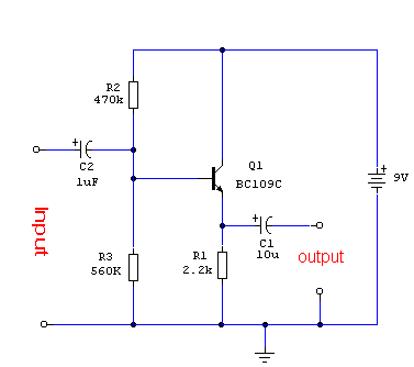
Reading Schematics
This document was created to address the numerous inquiries received about how to read a schematic. Learning to interpret a schematic diagram is akin to map reading; it requires understanding which wires connect to which components and identifying the start...
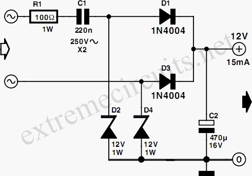
Low Power 12V Transformerless Power Supply
Many circuits can be powered directly from the mains with the aid of a series capacitor (C1). The disadvantage of this approach is that usually only one half cycle of the mains waveform can be used to produce a DC...
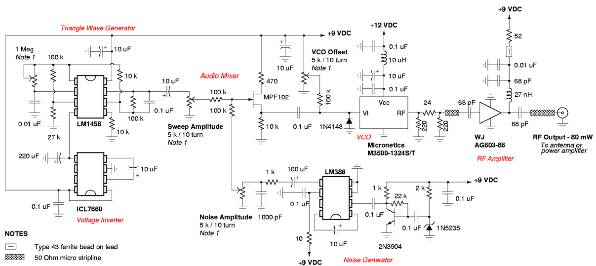
20 electrical documentation schematics
Note that the due dates for lectures 20-25 will be rescheduled to Wednesday at 1:00 PM. Download the notes for Topic 1: Basic Components (Listen to Dr. Stienecker) and Topic 2: Power and Connections (Listen to Dr. Stieneker). Students should...
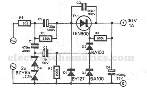
Transformerless Power Supply 30V 1A
This transformerless power supply circuit is designed for medium current applications. During the negative half period, the capacitor C5 is charged to the peak voltage of the network. The positive half wave will trigger the thyristor, allowing the electric charge...

Transformerless Power Supply
Transformerless Power Supply Circuit Diagram. The selection of the dropping capacitor and the circuit design requires technical knowledge and practical experience to achieve the desired voltage and current.
The transformerless power supply circuit is a compact and efficient solution for powering...
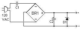
Transformerless Power Supply
I have received a few emails asking for a transformerless power supply. Here is such a supply. This supply uses no heavy step down transformer and has an extremely low parts count. The circuit can be built very small and...
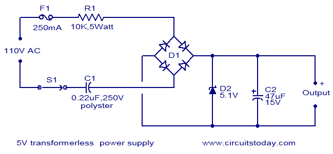
5V transformer less power supply
The circuit diagram illustrates a 5V transformerless power supply utilizing minimal components. The operation of this circuit is straightforward. Resistor R1 serves as a current limiter, while bridge D1 rectifies the mains voltage. The Zener diode regulates the output from...
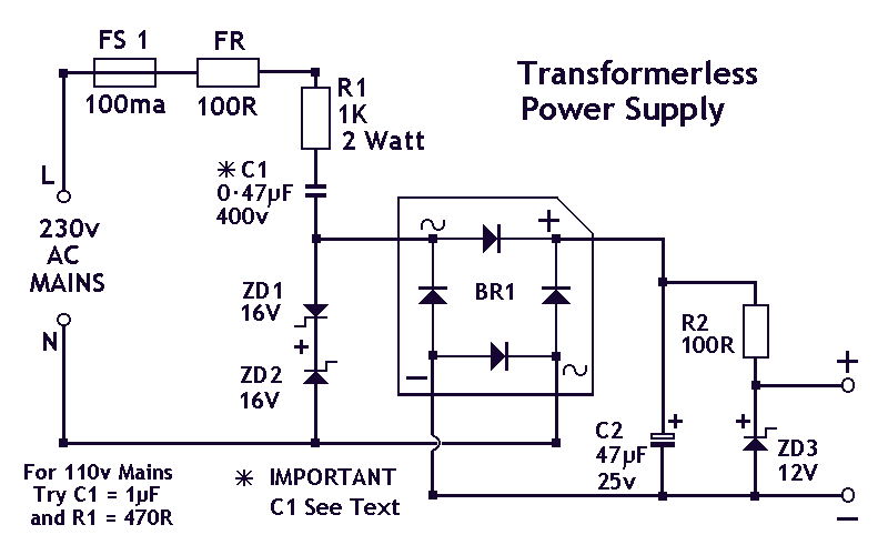
Transformerless PSU
This circuit will supply up to about 20mA at 12 volts. It uses capacitive reactance instead of resistance; and it doesn't generate very much heat. The circuit draws about 30mA AC. Always use a fuse and/or a fusible resistor to...

Low Cost Universal Battery Charger Schematic
This is a simple and low-cost NiCd and NiMH battery charger. The schematic diagram indicates that the charging current (I) should be set to 1/10 of the battery's rated capacity. For instance, if the battery has a rated capacity of...