


universal power supply with a safe high voltage capacitor
#universal power supply
#high voltage capacitor
#power supply circuit
#voltage regulation
#capacitor safety
#circuit diagram
#electronics
#electrical engineering
#power electronics
#HV capacitor
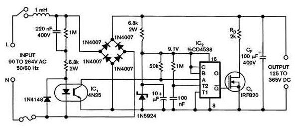
Description: Universal power supply with a safe high-voltage capacitor power supply. Refer to that page to read the explanation about the related circuit diagram of the above power supply.
The universal power supply circuit is designed to provide a stable output voltage across a variety of load conditions and input voltages. It typically includes a high-voltage capacitor, which is essential for energy storage and filtering, ensuring that the output remains smooth and consistent. The capacitor is charged from the mains supply, and its high voltage rating is crucial for safety and reliability in high-voltage applications.
The circuit generally consists of a transformer, which steps down the voltage from the mains supply to a manageable level. This is followed by a rectifier, which converts the AC voltage to DC. The output of the rectifier is then connected to the high-voltage capacitor, which smooths the rectified voltage. A voltage regulator may also be included to maintain a constant output voltage, regardless of variations in input voltage or load current.
Additional components such as fuses, diodes, and resistors are often incorporated for protection and stability. Fuses prevent overcurrent situations, while diodes ensure current flows in the correct direction and protect against voltage spikes. Resistors may be used for load balancing and to discharge the capacitor safely when the circuit is powered down.
Overall, the design of a universal power supply with a high-voltage capacitor is critical for applications requiring reliable power delivery, such as in laboratory settings, industrial equipment, and various electronic devices. Proper attention to component ratings and circuit layout is essential to ensure safety and performance.Universal power supply with a safe high-voltage capacitor power supply. Go to that page to read the explanation about above power supply related circuit diagram.
The universal power supply circuit is designed to provide a stable output voltage across a variety of load conditions and input voltages. It typically includes a high-voltage capacitor, which is essential for energy storage and filtering, ensuring that the output remains smooth and consistent. The capacitor is charged from the mains supply, and its high voltage rating is crucial for safety and reliability in high-voltage applications.
The circuit generally consists of a transformer, which steps down the voltage from the mains supply to a manageable level. This is followed by a rectifier, which converts the AC voltage to DC. The output of the rectifier is then connected to the high-voltage capacitor, which smooths the rectified voltage. A voltage regulator may also be included to maintain a constant output voltage, regardless of variations in input voltage or load current.
Additional components such as fuses, diodes, and resistors are often incorporated for protection and stability. Fuses prevent overcurrent situations, while diodes ensure current flows in the correct direction and protect against voltage spikes. Resistors may be used for load balancing and to discharge the capacitor safely when the circuit is powered down.
Overall, the design of a universal power supply with a high-voltage capacitor is critical for applications requiring reliable power delivery, such as in laboratory settings, industrial equipment, and various electronic devices. Proper attention to component ratings and circuit layout is essential to ensure safety and performance.Universal power supply with a safe high-voltage capacitor power supply. Go to that page to read the explanation about above power supply related circuit diagram.
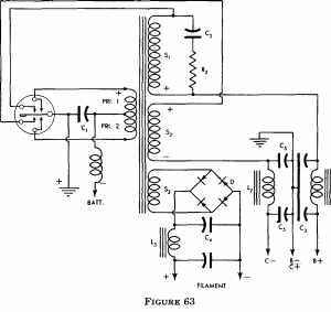
power supply design
The more one understands about any subject, the more interesting it becomes. As this article is read, it will be found that the subject of...
A comprehensive electronic schematic typically involves various components, each serving a specific function in the overall...
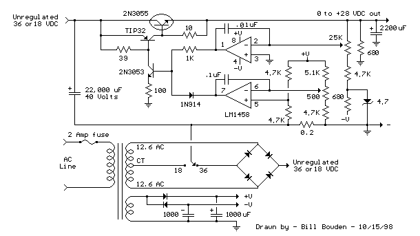
variable voltage and current power supply
An alternative method for utilizing operational amplifiers (op-amps) to regulate a power supply is illustrated below. The power transformer necessitates an additional winding to provide the op-amps with a bipolar voltage of +/- 8 volts. This negative voltage is also...
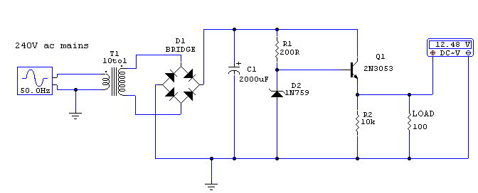
Regulated 12 Volt Supply
This circuit utilizes a 13-volt zener diode (D2) for voltage regulation. Approximately 0.7 volts are dropped across the base-emitter junction of the transistors, resulting in a higher current output of 12.3 volts. The circuit is capable of supplying loads up...
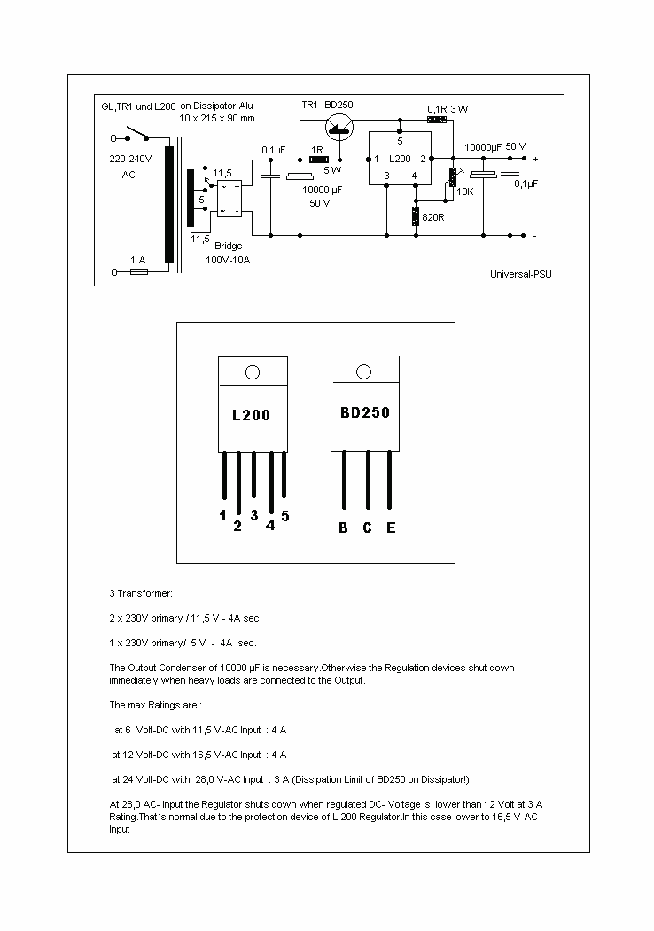
4 Amps Universal PSU
A Universal Power supply based on the L200 regulator, which includes an outboard pass transistor to boost output currents up to 4 amps.
The described universal power supply utilizes the L200 voltage regulator, renowned for its versatility in providing adjustable output...

capacitor Explaining a car voltage regulator circuit
The circuit regulates approximately 12V from the car battery down to 5V for use by an Atmel AVR microcontroller. The presence of two capacitors on each side of the linear regulator LM7805 raises questions regarding their purpose. It is suggested...
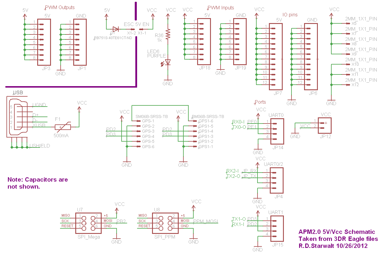
APM2.0 5V/Vcc Schematic
The PWM Output section has been separated into the upper left corner, delineated by a heavy purple line that is bridged by jumper JP1 on the APM2.0. This design choice highlights that diode D1 allows current to pass through JP1,...
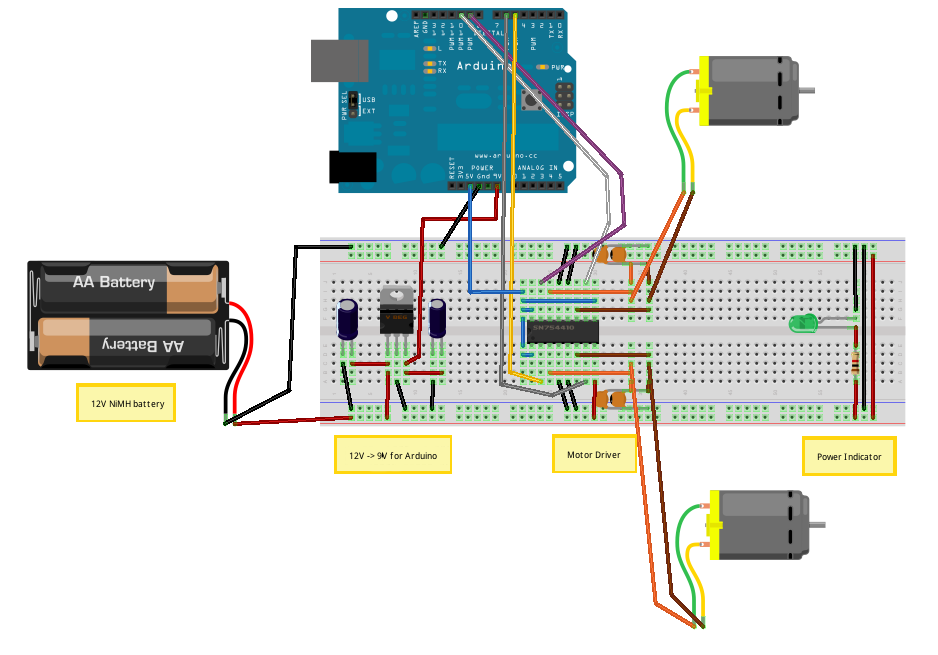
Voltage Regulators
Until Willow Garage was acquired, there was work as a Web Robotics Engineer. This title reflects a role as a full-stack engineer focused on real-time, distributed robot control. Notable projects include an XML-RPC server and client for Node.js, a deprecated...
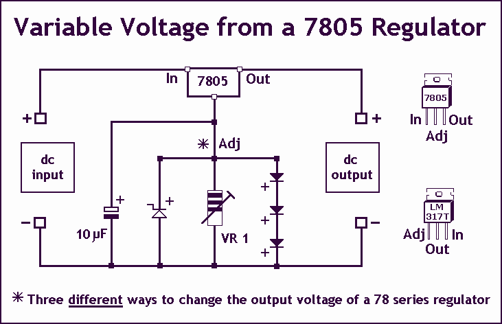
Variable Voltage Regulation
Controlling the output voltage from a regulator can be made variable in three ways:
1. Using a fixed reference zener diode to increase the output by the value of the zener
2. A variable resistor for variable output, note that...
protected
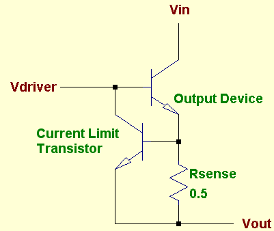
A voltage regulator is designed to provide a fixed voltage to any load. This inherently means it must supply the necessary current through that load to satisfy Ohm's Law, I = V/R. As the resistance (R) approaches zero, such as...