


1930 ~ 1990MHz narrow-band RF2320 linear amplification circuit diagram
#RF2320
#narrow-band
#linear amplifier
#1930-1990MHz
#RF signal
#amplification
#radio frequency
#signal input
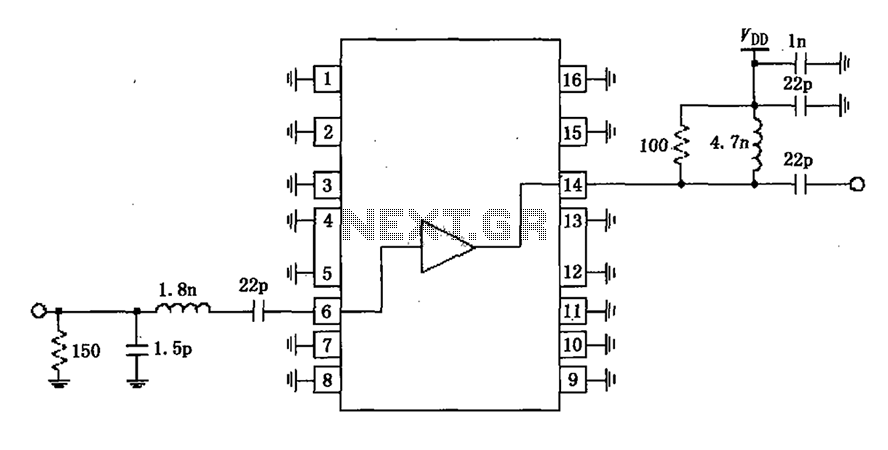
Description: A narrowband linear amplifier circuit configured with the RF2320 operates within a frequency range of 1930 to 1990 MHz. The radio frequency (RF) signal is input from a distance of 6 feet and is amplified by an internal amplifier located 14 feet from the input. The internal amplifier is directly coupled to the input, necessitating the addition of a blocking coupling capacitor. The typical gate voltage at the input terminal is 0V; however, increasing the external gate bias voltage will raise the current, albeit without enhancing the linearity of the amplifier. The output, located 14 feet away, provides both outputs and internal bias, but lacks DC blocking capacitors within the chip. Therefore, a 22pF capacitor is used as a DC blocking capacitor. An output matching network is employed to match the output impedance of the amplifier, ensuring maximum output power and efficiency.
The described narrowband linear amplifier circuit utilizes the RF2320, which is specifically designed for high-frequency applications. The operational frequency range of 1930 to 1990 MHz makes it suitable for various RF communication systems. The input RF signal is received from a distance of 6 feet, where it is amplified through the internal amplifier positioned 14 feet from the input source.
The direct coupling of the internal amplifier to the input signal path is an essential design choice, as it minimizes signal loss and preserves the integrity of the RF signal. However, this configuration requires the integration of a blocking coupling capacitor to prevent DC components from affecting the amplifier's performance. The typical gate voltage at the input terminal is set to 0V, establishing a baseline for signal amplification. Increasing the external gate bias voltage will lead to a rise in the output current; however, it is crucial to note that this adjustment does not enhance the linearity of the amplifier, which is a critical parameter in RF applications to ensure signal fidelity.
The output of the amplifier, located 14 feet away, is designed to provide both the amplified RF signal and the necessary internal bias. The absence of DC blocking capacitors within the RF2320 chip necessitates the use of an external 22pF capacitor. This capacitor serves as a DC blocking element, allowing only the AC components of the amplified signal to pass while preventing any DC offset from affecting downstream components.
To optimize performance, an output matching network is implemented to align the output impedance of the amplifier with the load impedance. This matching network is vital for achieving maximum output power and efficiency, which are critical for effective RF signal transmission. By ensuring that the amplifier is properly matched to its load, signal reflections are minimized, and power transfer is maximized, leading to improved overall system performance.1930 ~ 1990MHz as shown in Fig narrowband linear amplifier circuit configured by RF2320. Radio frequency (RF) signal input from 6 feet, after amplified by an amplifier 14 feet out. 6 feet and internal amplifier is directly coupled, so plus a blocking coupling capacitor. Typically, the gate voltage of the input terminal is 0V, but the external gate bias voltage increases will increase, which will increase while the current, but will not improve amplifier linearity. 14 feet while providing outputs and internal bias, not in the chip DC blocking capacitors, and the pin dc voltage, so a 22pF capacitor as a DC blocking capacitor.
Output matching network to match the output impedance of the amplifier, in order to obtain the maximum output power and efficiency.
The described narrowband linear amplifier circuit utilizes the RF2320, which is specifically designed for high-frequency applications. The operational frequency range of 1930 to 1990 MHz makes it suitable for various RF communication systems. The input RF signal is received from a distance of 6 feet, where it is amplified through the internal amplifier positioned 14 feet from the input source.
The direct coupling of the internal amplifier to the input signal path is an essential design choice, as it minimizes signal loss and preserves the integrity of the RF signal. However, this configuration requires the integration of a blocking coupling capacitor to prevent DC components from affecting the amplifier's performance. The typical gate voltage at the input terminal is set to 0V, establishing a baseline for signal amplification. Increasing the external gate bias voltage will lead to a rise in the output current; however, it is crucial to note that this adjustment does not enhance the linearity of the amplifier, which is a critical parameter in RF applications to ensure signal fidelity.
The output of the amplifier, located 14 feet away, is designed to provide both the amplified RF signal and the necessary internal bias. The absence of DC blocking capacitors within the RF2320 chip necessitates the use of an external 22pF capacitor. This capacitor serves as a DC blocking element, allowing only the AC components of the amplified signal to pass while preventing any DC offset from affecting downstream components.
To optimize performance, an output matching network is implemented to align the output impedance of the amplifier with the load impedance. This matching network is vital for achieving maximum output power and efficiency, which are critical for effective RF signal transmission. By ensuring that the amplifier is properly matched to its load, signal reflections are minimized, and power transfer is maximized, leading to improved overall system performance.1930 ~ 1990MHz as shown in Fig narrowband linear amplifier circuit configured by RF2320. Radio frequency (RF) signal input from 6 feet, after amplified by an amplifier 14 feet out. 6 feet and internal amplifier is directly coupled, so plus a blocking coupling capacitor. Typically, the gate voltage of the input terminal is 0V, but the external gate bias voltage increases will increase, which will increase while the current, but will not improve amplifier linearity. 14 feet while providing outputs and internal bias, not in the chip DC blocking capacitors, and the pin dc voltage, so a 22pF capacitor as a DC blocking capacitor.
Output matching network to match the output impedance of the amplifier, in order to obtain the maximum output power and efficiency.

METAL DETECTOR
When the receiver is tuned to a medium wave radio station, feedback howl caused by the transmitter may occur when the coil and radio are positioned above or near a metal object. The search head is constructed from a margarine...
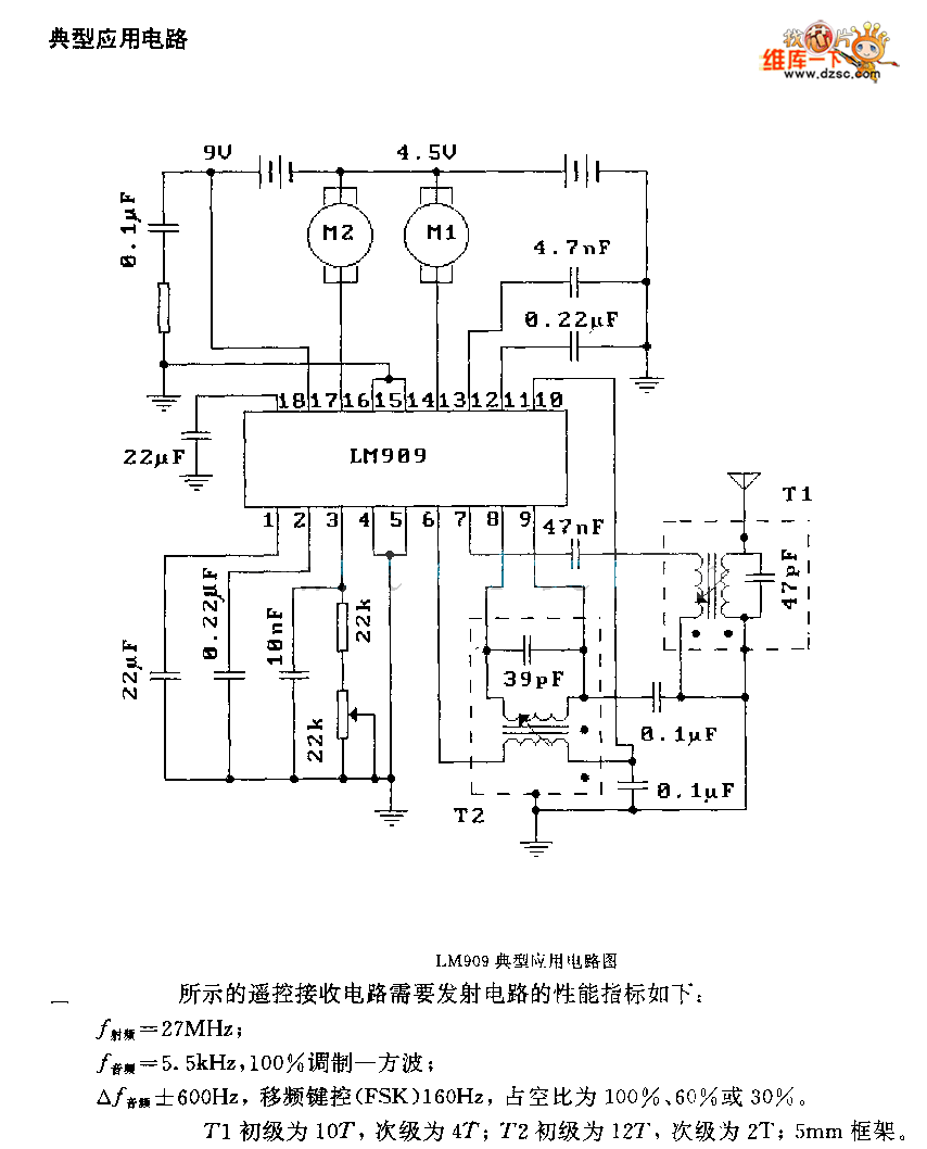
LM909 radio telecontrol receiving decoding circuit diagram
The performance indices of the telecontrol receiving decoding circuit are as follows: radio frequency (f) = 27 MHz, audio frequency (f) = 5.5 kHz, 100% modulation in square-wave form; radio frequency deviation is ±600 Hz, and the frequency shift keying...
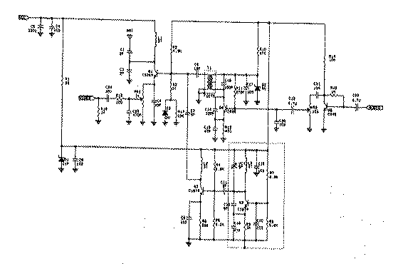
bugs
Radio transmitters for eavesdropping on private conversations and sending video pictures, battery-operated.
Radio transmitters designed for eavesdropping applications typically operate within specific frequency ranges to capture audio and video signals discreetly. These devices often utilize low-power RF (radio frequency) technology to...
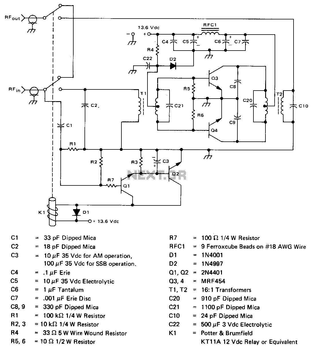
2-30Mhz-140w-linear-amplifier
The amplifier operates across the 2-30 MHz band with a relatively flat gain response and reaches gain saturation at approximately 210 W of output power. Both input and output transformers have a 4:1 turns ratio (16:1 impedance ratio) to achieve...
60W Linear amplifiers
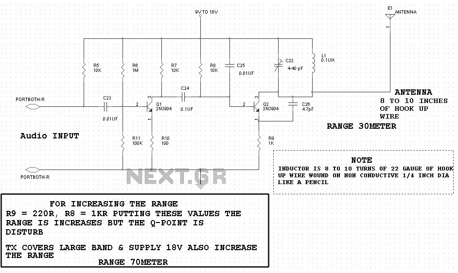
The 60 Watt linear amplifier is a straightforward all-solid-state circuit utilizing the power MOSFET IRF840. The IRF series of power transistors are available in various voltage and power ratings. A single IRF840 can handle a maximum power output of 125...
6M 100W Linear Amplifier
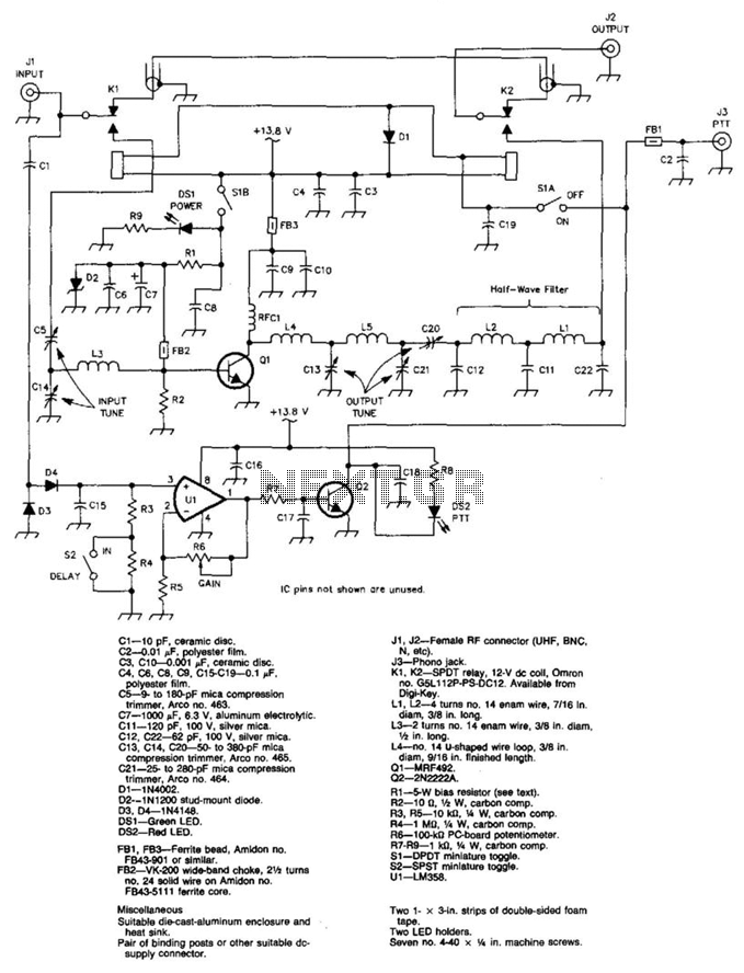
A 100 W output at 50 MHz is available from this circuit. U1 and Q2 form a T-R relay driver, switching the amplifier on when RF input at J1 is sensed. During receive periods, J1 and J2 are directly connected....
500 metre radio data link
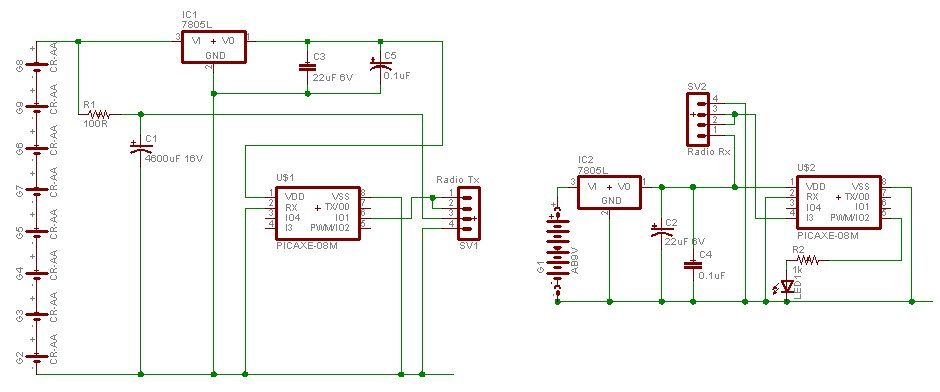
A water tank, dam, or gate can be monitored for vehicle detection without the need for wired connections through the garden. This guide demonstrates how to transmit data reliably over a distance of 500 meters using PICAXE microcontroller chips and...
10 To 15W Atv Linear Amplifier
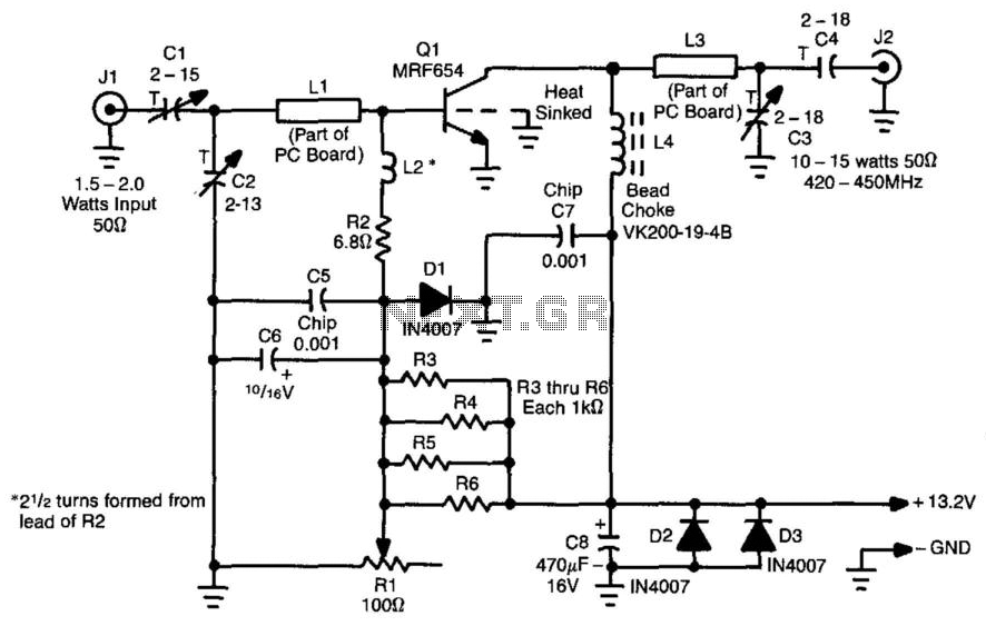
This amplifier is designed for applications requiring a peak-envelope-power (PEP) signal in the range of 10 to 15 watts, specifically within the 420 to 520 MHz frequency range. Components CI, C2, and LI create a matching network for amplifier Q1....
More About Oscillators
Online Electronics Course covering the Science of Radio Frequency Engineering, including topics such as Electronics, Microwave Technology, Waveguides, Antennas, Tubes, Historical Context, Klystrons, Magnetrons, Traveling Wave Tubes (TWT), Internet of Things (IoT), Klystrodes, Broadcast Equipment, and Repair Techniques.
The online electronics...