


75 impedance RF2320 linear amplification circuit diagram
#RF2320
#linear amplifier
#75 impedance
#RF circuit
#connector
#amplification
#signal processing
#high frequency
#circuit diagram
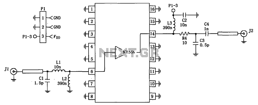
Description: The impedance linear amplifier circuit is illustrated in FIG 75 and is configured using the RF2320 component. Connectors J1 and J2 are 75-ohm connectors.
The impedance linear amplifier circuit designed with the RF2320 is intended for applications requiring high fidelity and low distortion signal amplification. This circuit is particularly suitable for radio frequency (RF) applications where maintaining the integrity of the signal is crucial. The RF2320 is a versatile amplifier capable of providing a wide bandwidth and is optimized for 75-ohm systems, making it ideal for television and cable applications.
The circuit's layout typically includes two 75-ohm connectors, J1 and J2, which serve as the input and output ports, respectively. These connectors ensure that the amplifier is properly matched to the characteristic impedance of the transmission line, minimizing reflections and maximizing power transfer.
In operation, the RF2320 amplifies the input signal while maintaining a linear response across the desired frequency range. The design may include additional components such as resistors and capacitors to stabilize the amplifier, filter out unwanted frequencies, and enhance overall performance. Careful attention must be paid to the power supply and grounding arrangements to prevent noise and ensure optimal operation.
Overall, this impedance linear amplifier circuit is a critical component in RF signal processing, providing robust amplification while adhering to the necessary impedance standards for effective transmission and reception of signals. As shown in FIG 75 impedance linear amplifier circuit configured by RF2320. J1 and J2 are 75 F connector.
The impedance linear amplifier circuit designed with the RF2320 is intended for applications requiring high fidelity and low distortion signal amplification. This circuit is particularly suitable for radio frequency (RF) applications where maintaining the integrity of the signal is crucial. The RF2320 is a versatile amplifier capable of providing a wide bandwidth and is optimized for 75-ohm systems, making it ideal for television and cable applications.
The circuit's layout typically includes two 75-ohm connectors, J1 and J2, which serve as the input and output ports, respectively. These connectors ensure that the amplifier is properly matched to the characteristic impedance of the transmission line, minimizing reflections and maximizing power transfer.
In operation, the RF2320 amplifies the input signal while maintaining a linear response across the desired frequency range. The design may include additional components such as resistors and capacitors to stabilize the amplifier, filter out unwanted frequencies, and enhance overall performance. Careful attention must be paid to the power supply and grounding arrangements to prevent noise and ensure optimal operation.
Overall, this impedance linear amplifier circuit is a critical component in RF signal processing, providing robust amplification while adhering to the necessary impedance standards for effective transmission and reception of signals. As shown in FIG 75 impedance linear amplifier circuit configured by RF2320. J1 and J2 are 75 F connector.
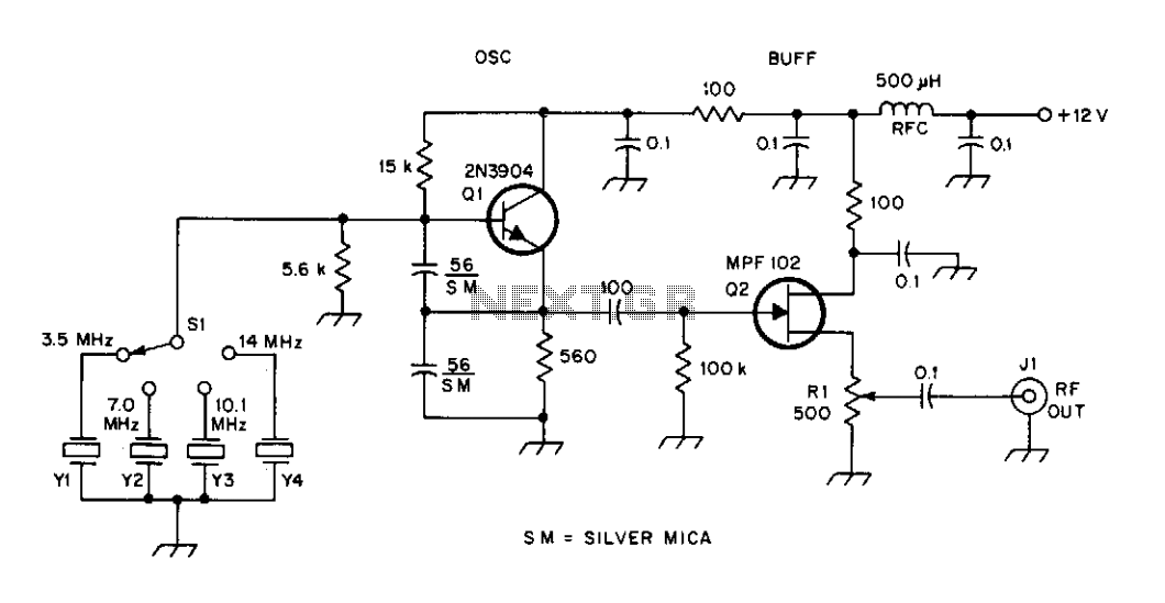
High frequency signal generator
A tapped-coil Colpitts oscillator is utilized at Q1 to deliver four tuning ranges: 1.7 to 3.131 MHz, 3.0 to 5.6 MHz, 5.0 to 12 MHz, and 11.5 to 31 MHz. A Zener diode (D2) is incorporated at Q1 to reduce...
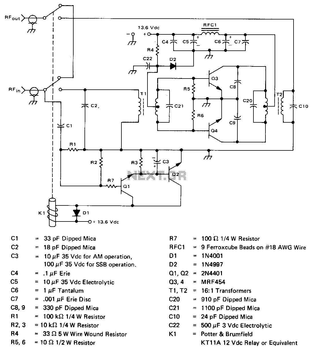
2-30Mhz-140w-linear-amplifier
The amplifier operates across the 2-30 MHz band with a relatively flat gain response and reaches gain saturation at approximately 210 W of output power. Both input and output transformers have a 4:1 turns ratio (16:1 impedance ratio) to achieve...
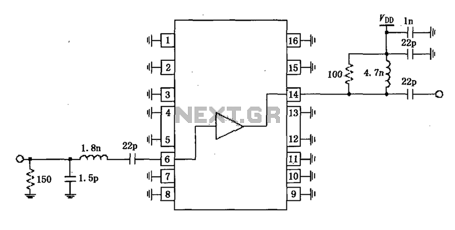
1930 ~ 1990MHz narrow-band RF2320 linear amplification circuit diagram
A narrowband linear amplifier circuit configured with the RF2320 operates within a frequency range of 1930 to 1990 MHz. The radio frequency (RF) signal is input from a distance of 6 feet and is amplified by an internal amplifier located...
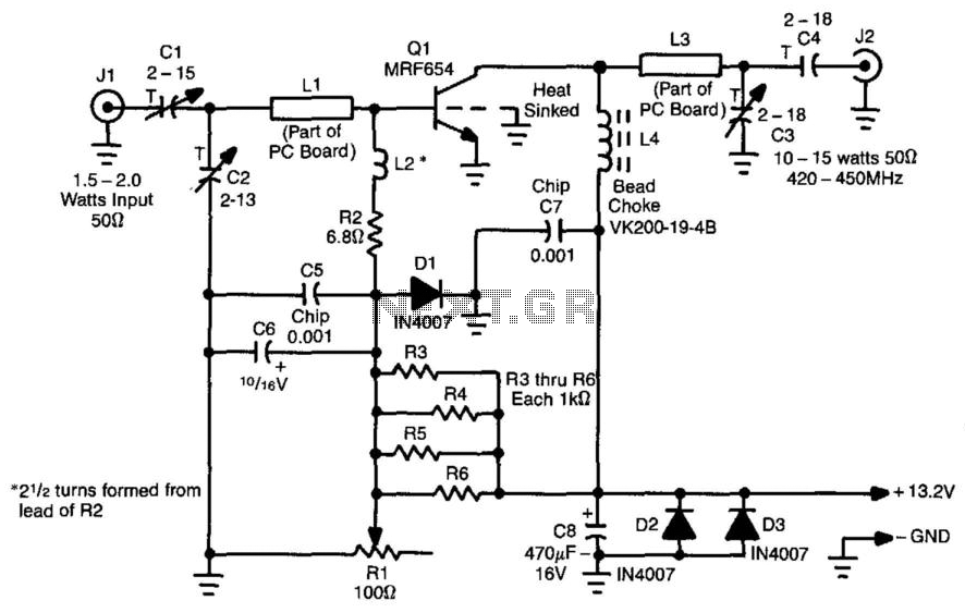
10 To 15W Atv Linear Amplifier
This amplifier is designed for applications requiring a peak-envelope-power (PEP) signal in the range of 10 to 15 watts, specifically within the 420 to 520 MHz frequency range. Components CI, C2, and LI create a matching network for amplifier Q1....
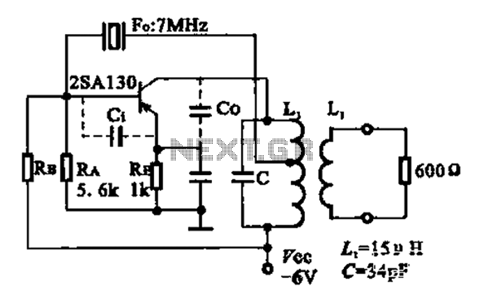
7MHz high frequency carrier oscillator
The 2SA130 transistor is used in an oscillator circuit with an oscillation frequency of 7 MHz. The power supply voltage is 6V, and the load is a frequency-selective resonant circuit with a quality factor of 600.
The circuit utilizes the 2SA130...
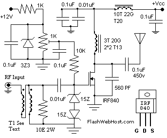
60 WATTS LINEAR AMPLIFIER
The 60 Watt linear amplifier is a simple all solid state circuit using power mosfet IRF840. The IRF series of power transistors are available in various voltage and power ratings. A single IRF840 can handle a maximum power output of...
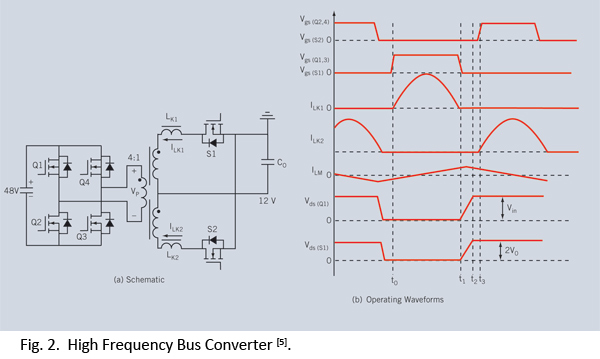
egan fet silicon power shoot out volume 10 high frequency resonant converters
Distributed power systems are commonly used in telecommunications, networking, and high-end server applications, utilizing a 48 V bus voltage derived from the telecom industry. This 48 V bus supplies several isolated point-of-load (POL) converters that power the end loads, with...
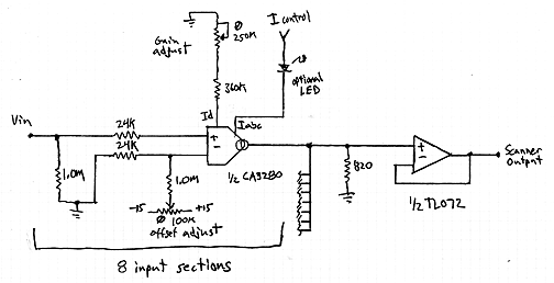
Interpolating Scanner Circuit
This design is for an interpolating scanner, a circuit featuring multiple signal inputs, a control voltage input, and a signal output. The output selectively transitions between inputs, smoothly fading from one to the next as the control voltage increases. A...
7MHz high frequency carrier oscillator
The 2SA130 transistor is used in an oscillator circuit with an oscillation frequency of 7 MHz. The power supply voltage is 6V, and the load is a frequency-selective resonant circuit with a quality factor of 600.
The circuit utilizes the 2SA130...