


AM circuit by MC1496
#AM circuit
#MC1496
#analog multiplier
#carrier channel
#RF modulation
#integrated circuit
#communication
#signal processing
#radio
#electronics
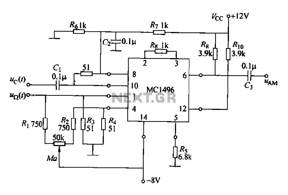
Description: The configuration of the AM MC1496 analog multiplier integrated circuit is illustrated in Figure 21-39. It features a two-input channel where the DC levels of the pins are set at 6V, allowing it to function as a carrier channel for two input channels. The Y input has an external connection that maintains a zero circuit. By adjusting a potentiometer, a potential of 50kΩ can be achieved, which is higher than the zero level. The modulation signal u(t) is superimposed with the DC input voltage UY of the Y channel. The potentiometer can be adjusted to modify the modulation index Ma. The output terminal connects to a bandpass filter that is tuned to the carrier frequency. A negative feedback resistor connects to the Y channel. The circuit depicted in Figure 21-39 represents a double-sideband amplitude modulation circuit. The potentiometer adjustment aims to ensure that the DC potential difference at the Y channel remains at zero, allowing only the AC modulation signal to be present at the Y-channel input. To minimize the current flowing through the potentiometer and facilitate accurate zeroing, two 750Ω resistors can be added, with each resistor being 10kΩ.
The AM MC1496 analog multiplier integrated circuit is designed for applications involving amplitude modulation, particularly in communication systems where signal integrity is crucial. The circuit operates by utilizing two input channels, allowing for the modulation of a carrier signal. The configuration ensures that the DC bias level is correctly set to 6V, which is vital for the proper functioning of the multiplier.
The Y input is particularly important as it allows for the superimposition of an AC modulation signal onto the DC input voltage. By employing a potentiometer, users can finely tune the modulation index, which directly affects the depth of modulation and, consequently, the quality of the transmitted signal. This tuning capability is essential in optimizing the performance of the modulation process.
The output of the circuit is connected to a bandpass filter, which is crucial for isolating the desired frequency components of the modulated signal while attenuating unwanted frequencies. The tuning of this filter is aligned with the carrier frequency, ensuring that the output signal maintains its integrity and is suitable for further processing or transmission.
Negative feedback is implemented through a resistor connected to the Y channel, which stabilizes the circuit and enhances linearity. This feedback mechanism is important for reducing distortion and improving the overall performance of the modulation process.
To achieve precise control over the input signal levels, the potentiometer is adjusted to maintain a zero DC potential difference at the Y channel. This adjustment allows only the AC modulation signal to pass through, ensuring that the output is a clean representation of the desired modulated signal.
In scenarios where the potentiometer's current needs to be minimized for accurate adjustments, the addition of two 750Ω resistors is recommended. This configuration helps in reducing the load on the potentiometer, facilitating easier and more accurate tuning to achieve the desired modulation characteristics.
Overall, the AM MC1496 integrated circuit configuration as described offers a robust solution for amplitude modulation applications, providing flexibility in tuning and ensuring high-quality signal transmission.AM MC1496 analog multiplier integrated circuit configuration shown in Figure 21-39. Channel two-input, ? pin DC bits are 6V, can be used as a carrier channel two input channels } Y input O, feet between external have zero circuit, by adjusting potentiometer allows 50kn potential than O foot foot high Uy, the modulation signal u ( ) is superimposed with the DC input voltage UY Y channel. Adjust the potentiometer to change the modulation index Ma. Output terminal, feet to bandpass filter tuned to the carrier frequency., feet between the outer negative feedback resistor connected to the Y channel.
The circuit shown indiscriminately 21-39 double-sideband amplitude modulation circuit can be composed, adjust the potentiometer is intended to make the Y channel O, feet between the DC potential difference is zero, the Y-channel input signal only the AC modulation signal. In order to reduce the current flowing through the potentiometer, accurate and easy to zero, can increase two 75051 resistor, such as increased each lOkn.
The AM MC1496 analog multiplier integrated circuit is designed for applications involving amplitude modulation, particularly in communication systems where signal integrity is crucial. The circuit operates by utilizing two input channels, allowing for the modulation of a carrier signal. The configuration ensures that the DC bias level is correctly set to 6V, which is vital for the proper functioning of the multiplier.
The Y input is particularly important as it allows for the superimposition of an AC modulation signal onto the DC input voltage. By employing a potentiometer, users can finely tune the modulation index, which directly affects the depth of modulation and, consequently, the quality of the transmitted signal. This tuning capability is essential in optimizing the performance of the modulation process.
The output of the circuit is connected to a bandpass filter, which is crucial for isolating the desired frequency components of the modulated signal while attenuating unwanted frequencies. The tuning of this filter is aligned with the carrier frequency, ensuring that the output signal maintains its integrity and is suitable for further processing or transmission.
Negative feedback is implemented through a resistor connected to the Y channel, which stabilizes the circuit and enhances linearity. This feedback mechanism is important for reducing distortion and improving the overall performance of the modulation process.
To achieve precise control over the input signal levels, the potentiometer is adjusted to maintain a zero DC potential difference at the Y channel. This adjustment allows only the AC modulation signal to pass through, ensuring that the output is a clean representation of the desired modulated signal.
In scenarios where the potentiometer's current needs to be minimized for accurate adjustments, the addition of two 750Ω resistors is recommended. This configuration helps in reducing the load on the potentiometer, facilitating easier and more accurate tuning to achieve the desired modulation characteristics.
Overall, the AM MC1496 integrated circuit configuration as described offers a robust solution for amplitude modulation applications, providing flexibility in tuning and ensuring high-quality signal transmission.AM MC1496 analog multiplier integrated circuit configuration shown in Figure 21-39. Channel two-input, ? pin DC bits are 6V, can be used as a carrier channel two input channels } Y input O, feet between external have zero circuit, by adjusting potentiometer allows 50kn potential than O foot foot high Uy, the modulation signal u ( ) is superimposed with the DC input voltage UY Y channel. Adjust the potentiometer to change the modulation index Ma. Output terminal, feet to bandpass filter tuned to the carrier frequency., feet between the outer negative feedback resistor connected to the Y channel.
The circuit shown indiscriminately 21-39 double-sideband amplitude modulation circuit can be composed, adjust the potentiometer is intended to make the Y channel O, feet between the DC potential difference is zero, the Y-channel input signal only the AC modulation signal. In order to reduce the current flowing through the potentiometer, accurate and easy to zero, can increase two 75051 resistor, such as increased each lOkn.
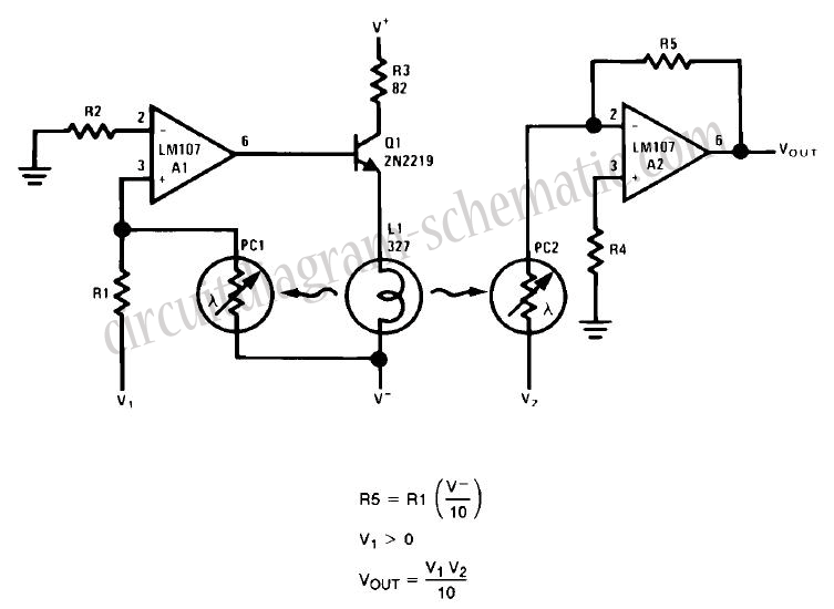
Simple Analog Multiplier Circuit Using LM107
This circuit is a simple analog multiplier. The operation of the circuit can be understood by considering A2 as a controlled gain amplifier. It involves components such as an analog multiplier, a log-antilog circuit, and a summing junction, along with...
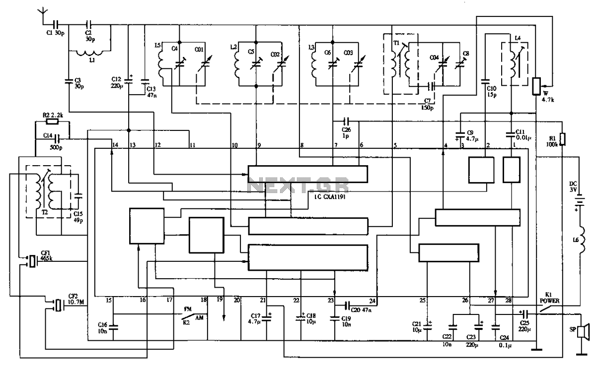
Desheng R-202T type two-band radio circuit diagram
The circuit diagram of the Desheng R-202T type two-band radio is as follows.
The Desheng R-202T is a two-band radio receiver designed to operate on both AM and FM frequencies. The circuit typically includes several key components that facilitate the tuning...
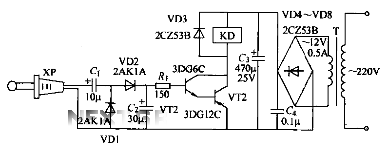
Radio remote control circuit
The receiver circuit depicted in the figure requires the insertion of a plug into the radio headphone jack. When the radio receiver detects a signal from the transmitter, an audio signal is output from the jack. This signal is then...
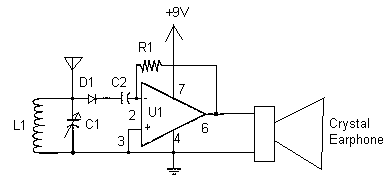
crystal Op Amp Radio
Here is a simple radio that is easy to build and inexpensive. In fact, you probably have all the parts you need in your junk box. You'll be surprised at the great reception with this little set. More: The antenna...
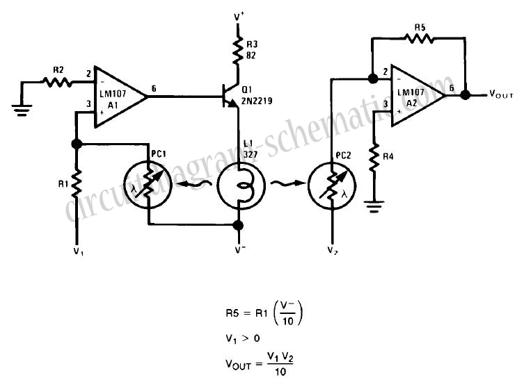
Simple Analog Multiplier Circuit Using LM107
This circuit is a simple analog multiplier. The operation of the circuit can be understood by considering A2 as a controlled gain amplifier that amplifies V2, with its gain dependent on the ratio of the resistance of PC2 to R5....
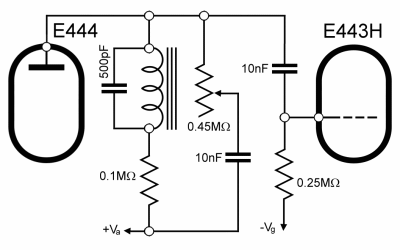
SV3 Radio Magnadyne Radio
Most models produced in the 1930s utilize similar circuits, particularly in the RF section, which follows a common LW-MW-SW scheme. Variations among different models primarily stem from the inclusion or exclusion of variable selectivity control, the sophistication of tone controls,...
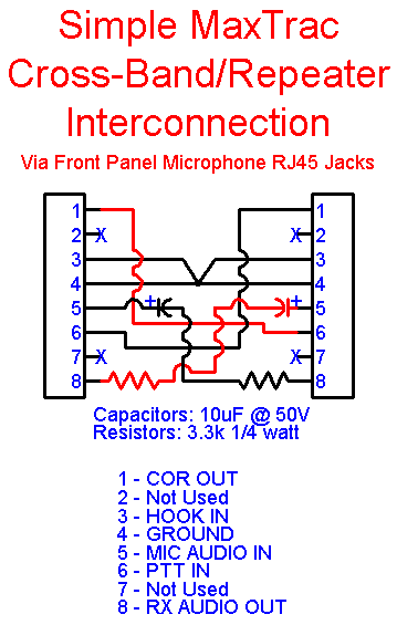
Interfacing MaxTrac Mobile Radios to Repeater Controllers
This article outlines a reliable, straightforward, and universal method for interfacing Motorola mobile radios from the MaxTrac, Radius, and GM300 series with common repeater controllers. The information provided is also relevant for radio interfaces used in IRLP or EchoLink applications....
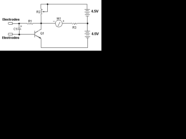
simple radio schematic
This page is provided to the domain owner free by Sedo's Domain Parking. Disclaimer: The domain owner and Sedo maintain no relationship with third-party advertisers. References to any specific service or trademark are not controlled by Sedo or the domain...
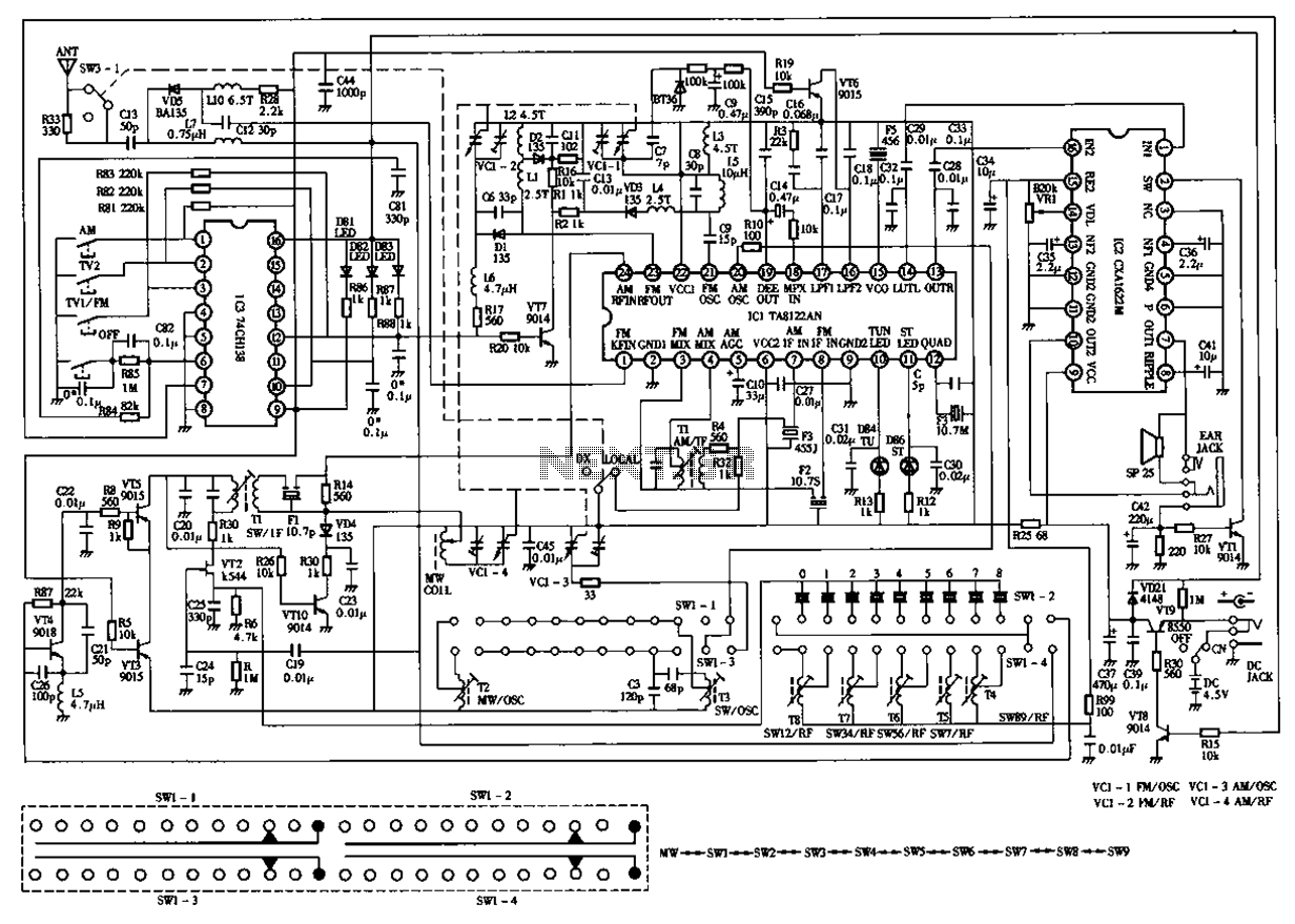
Desheng 119 700 High sensitivity l2-band stereo radio circuit diagram
The circuit diagram for the Desheng 119 700 type FM, TV sound, medium wave, and short wave high sensitivity L2-band stereo radio is presented below.
The Desheng 119 700 type radio circuit is designed to receive various frequency bands including FM,...