


BA1404 FM Stereo modulator circuit design electronic project
#FM stereo
#modulator
#BA1404
#transmitter
#broadcast
#stereo audio
#RF
#75-108MHz
#electronic project
#simple circuit
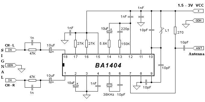
Description: The BA1404 can be utilized to create a simple and effective FM stereo modulator electronic project. This BA1404 FM stereo modulator device operates within the FM broadcast band (75-108 MHz) and requires only a few common external components. The BA1404 FM stereo modulator IC encompasses all necessary components to design a straightforward, high-efficiency stereo transmitter circuit. The IC includes a stereo modulator that generates stereo composite signals, an FM modulator that produces FM signals, and an RF amplifier. The FM stereo transmitter generates composite signals composed of a main (L+R) signal, a sub (L-R) signal, and a pilot (19 kHz) signal utilizing a 38 kHz crystal oscillator.
The BA1404 FM stereo modulator is designed for applications in the FM broadcast band, making it suitable for amateur radio projects and personal audio transmission systems. The circuit primarily consists of the BA1404 IC, which integrates several functions, thereby reducing the number of external components required for operation.
The stereo modulator within the BA1404 creates composite audio signals by combining the left (L) and right (R) audio channels. This process produces a main signal (L+R) and a sub signal (L-R), which are essential for stereo sound reproduction. The pilot signal, generated at 19 kHz, serves as a synchronization reference for FM receivers, ensuring proper demodulation of the stereo signal.
The FM modulator section of the BA1404 takes the composite signals and modulates them onto a carrier frequency within the FM broadcast band. This modulation process enables the transmission of audio signals over the airwaves, allowing for wireless audio broadcasting. The RF amplifier enhances the output signal, ensuring sufficient power for effective transmission distance.
To implement this circuit, a 38 kHz crystal oscillator is required, which provides stability and precision in frequency generation. The choice of external components, such as capacitors and resistors, will influence the performance of the transmitter, including frequency stability and modulation depth. Proper layout and shielding are also critical to minimize interference and ensure clear audio quality.
Overall, the BA1404 FM stereo modulator is an efficient solution for creating a compact FM transmitter capable of delivering high-quality stereo audio signals. Its simplicity and integration of multiple functions make it an attractive choice for hobbyists and engineers working in the field of wireless audio transmission.Using BA1404 can be designed a very simple and useful fm stereo modulator electronic project. This BA1404 fm stereo modulator device works in FM broadcast band ( 75- 108MHz) and require few external common components. The BA1404 fm stereo modulator Ic contains all parts needed to design an simple high efficiency stereo transmitter circuit.
This IC contains a stereo modulator that creates stereo composites signals, an FM modulator that creates FM signals and a RF amplifier. The fm stereo transmitter develops composite signals made up of a main(L+R) signal and sub(L-R) signal and a pilot (19KHz) signal using a 38KHz crystal oscillators.
The BA1404 FM stereo modulator is designed for applications in the FM broadcast band, making it suitable for amateur radio projects and personal audio transmission systems. The circuit primarily consists of the BA1404 IC, which integrates several functions, thereby reducing the number of external components required for operation.
The stereo modulator within the BA1404 creates composite audio signals by combining the left (L) and right (R) audio channels. This process produces a main signal (L+R) and a sub signal (L-R), which are essential for stereo sound reproduction. The pilot signal, generated at 19 kHz, serves as a synchronization reference for FM receivers, ensuring proper demodulation of the stereo signal.
The FM modulator section of the BA1404 takes the composite signals and modulates them onto a carrier frequency within the FM broadcast band. This modulation process enables the transmission of audio signals over the airwaves, allowing for wireless audio broadcasting. The RF amplifier enhances the output signal, ensuring sufficient power for effective transmission distance.
To implement this circuit, a 38 kHz crystal oscillator is required, which provides stability and precision in frequency generation. The choice of external components, such as capacitors and resistors, will influence the performance of the transmitter, including frequency stability and modulation depth. Proper layout and shielding are also critical to minimize interference and ensure clear audio quality.
Overall, the BA1404 FM stereo modulator is an efficient solution for creating a compact FM transmitter capable of delivering high-quality stereo audio signals. Its simplicity and integration of multiple functions make it an attractive choice for hobbyists and engineers working in the field of wireless audio transmission.Using BA1404 can be designed a very simple and useful fm stereo modulator electronic project. This BA1404 fm stereo modulator device works in FM broadcast band ( 75- 108MHz) and require few external common components. The BA1404 fm stereo modulator Ic contains all parts needed to design an simple high efficiency stereo transmitter circuit.
This IC contains a stereo modulator that creates stereo composites signals, an FM modulator that creates FM signals and a RF amplifier. The fm stereo transmitter develops composite signals made up of a main(L+R) signal and sub(L-R) signal and a pilot (19KHz) signal using a 38KHz crystal oscillators.
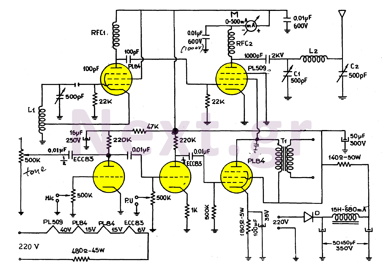
Simple Valve MW Transmitter circuit 30W
The simplicity of this transmitter, combined with its high performance, makes it particularly interesting. It has an output power of approximately 30 W, and under normal conditions, with the appropriate antenna and handling, it can achieve a range of 30...
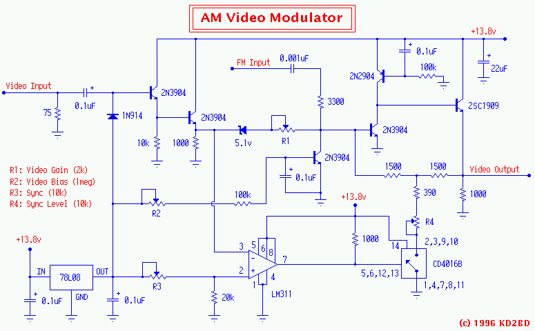
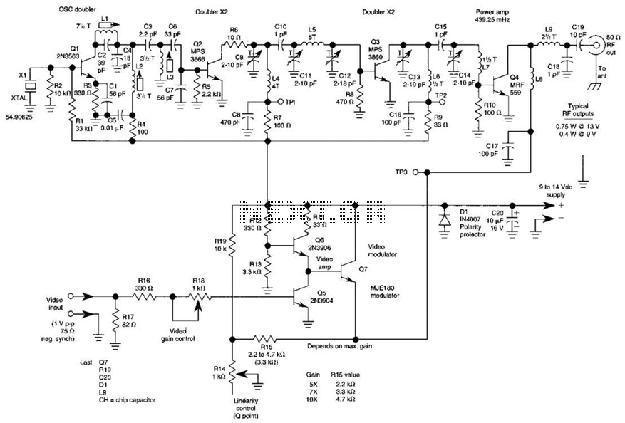
The KD2BD ATV AM Video Modulator
A 2N3904 in the base circuit sets the Q point of the amplifier. FM subcarrier audio at 4.5 MHz is also injected at this point through a 3300 ohm resistor and a DC blocking capacitor. A high frequency 5-watt RF...
valved transmitter for 3.5 MHz
This transmitter project is a highly efficient, rugged, and simple low-power continuous wave (C.W.) unit delivering more than 10W. It is crystal-controlled with stabilized high tension (H.T.) and features a buffer stage between the crystal oscillator and power amplifier stages,...
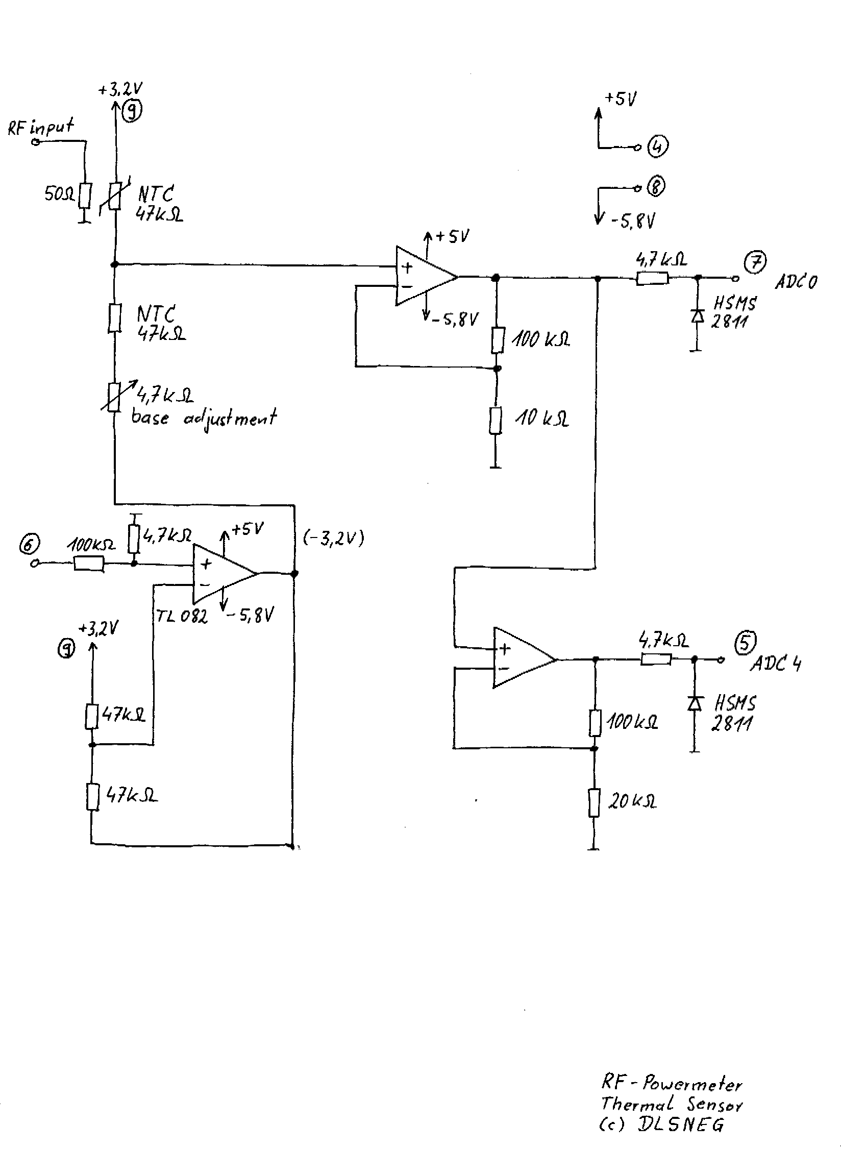
handheld RF-Powermeter for multiple sensors up to 12 GHz
A few years ago, a diode-sensor based RF power meter was built using a 68HC11 microprocessor. Prior to that, an analog RF power meter with a thermal power sensor was developed. The datasheets for logarithmic amplifiers, which promised a measurement...
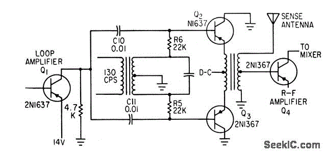
BALANCED MODULATOR FOR ADF
Combines signals from loop and sense antennas of an automatic direction finder to produce a 130-cps output with the correct phase for driving the rotor of a resolver to achieve a null position.
The circuit described is integral to the operation...
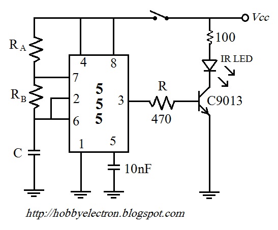
remote control circuit
The remote control circuit comprises two main components: a transmitter and a receiver. The transmitter circuit is controlled by an NE555 integrated circuit (IC), while the receiver operates based on the frequency of the signal emitted by the transmitter. It...
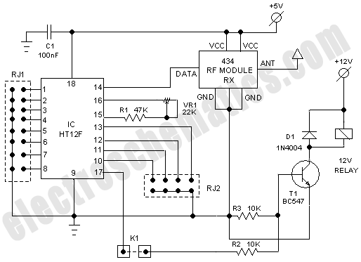
RF Based Wireless Remote Control Switch
It is often necessary to control electrical appliances remotely, even when there is no direct line of sight between the transmitter and receiver.
In modern electronic applications, remote control systems are increasingly utilized for various purposes, including home automation, industrial control,...
10M Dsb Qrp Transmitter With Vfo Circuit
The three schematics illustrate three building blocks for a 10-meter SSB transmitter. These blocks can also be utilized independently as circuit modules for other transmitters. The VFO board incorporates an FET transmission oscillator, with the VFO signal being mixed in...

double sideband suppressed carrier modulator
The basic current prevents any carrier from being present in the output. By applying offsets to the carrier differential pairs, controlled amounts of carrier can be introduced at the output.
In electronic circuit design, the concept of managing carrier signals is...