


Full-band phase locked loop circuit diagram fast
#phase locked loop
#voltage controlled oscillator
#TTL latch
#comparator
#frequency synthesis
#RF circuit
#signal generation
#Am686
#latch circuit
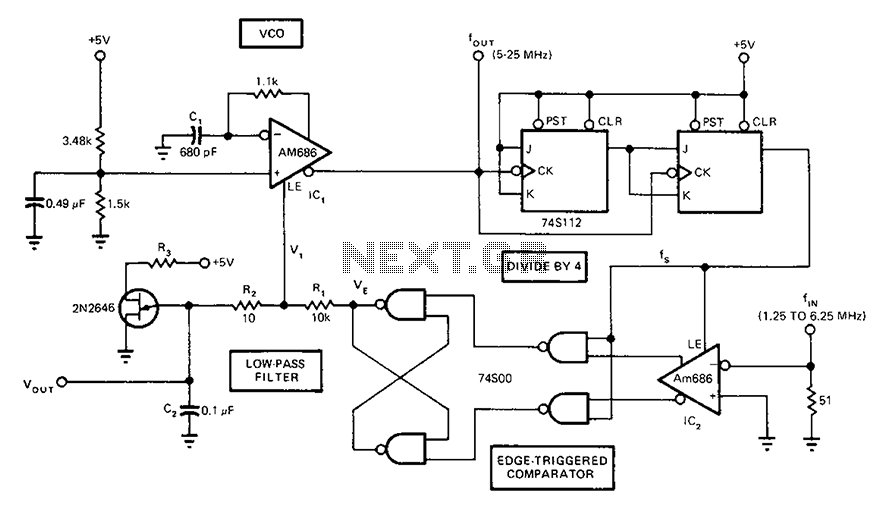
Description: A circuit diagram of a phase-locked loop utilizes an AM686 latched comparator as a voltage-controlled oscillator, along with a TTL latch connected to generate edge-triggered comparators. The VCO and its comparison with the low-pass filter consisting of R1, R2, and C2 form the PLL.
The presented circuit diagram outlines a phase-locked loop (PLL) configuration that integrates an AM686 latched comparator functioning as the voltage-controlled oscillator (VCO). This VCO is pivotal in generating a frequency output that is dependent on the input voltage. The circuit also incorporates a TTL latch, which is crucial for producing edge-triggered comparisons. This arrangement allows for precise synchronization of the output frequency with a reference frequency.
In this PLL design, the low-pass filter plays a significant role in smoothing the output signal from the VCO. The components R1, R2, and C2 are arranged to form a filter that effectively reduces high-frequency noise, ensuring that only the desired frequency components are passed through. The low-pass filter's cutoff frequency can be adjusted by selecting appropriate values for R1, R2, and C2, which directly influences the loop's stability and response time.
The operation of the PLL involves the VCO generating a signal that is compared to a reference signal. The edge-triggered comparators, enabled by the TTL latch, facilitate this comparison by detecting the phase difference between the two signals. The output of the comparator is then fed back to the VCO, adjusting its frequency to minimize the phase difference. This feedback mechanism is essential for maintaining lock and achieving stable frequency output.
Overall, this PLL circuit is designed for applications requiring precise frequency control and stability, making it suitable for various electronic systems where synchronization of signals is critical.A circuit diagram of a phase locked loop fast the whole band takes a Am686 latched comparator as voltage controlled oscillator, and the other with a TTL latch coupled to genera te edge-triggered comparators. VCO and comparison with the low-pass filter R1, R2, C2 link, constitute PLL.
The presented circuit diagram outlines a phase-locked loop (PLL) configuration that integrates an AM686 latched comparator functioning as the voltage-controlled oscillator (VCO). This VCO is pivotal in generating a frequency output that is dependent on the input voltage. The circuit also incorporates a TTL latch, which is crucial for producing edge-triggered comparisons. This arrangement allows for precise synchronization of the output frequency with a reference frequency.
In this PLL design, the low-pass filter plays a significant role in smoothing the output signal from the VCO. The components R1, R2, and C2 are arranged to form a filter that effectively reduces high-frequency noise, ensuring that only the desired frequency components are passed through. The low-pass filter's cutoff frequency can be adjusted by selecting appropriate values for R1, R2, and C2, which directly influences the loop's stability and response time.
The operation of the PLL involves the VCO generating a signal that is compared to a reference signal. The edge-triggered comparators, enabled by the TTL latch, facilitate this comparison by detecting the phase difference between the two signals. The output of the comparator is then fed back to the VCO, adjusting its frequency to minimize the phase difference. This feedback mechanism is essential for maintaining lock and achieving stable frequency output.
Overall, this PLL circuit is designed for applications requiring precise frequency control and stability, making it suitable for various electronic systems where synchronization of signals is critical.A circuit diagram of a phase locked loop fast the whole band takes a Am686 latched comparator as voltage controlled oscillator, and the other with a TTL latch coupled to genera te edge-triggered comparators. VCO and comparison with the low-pass filter R1, R2, C2 link, constitute PLL.
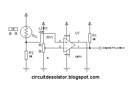
simple analog comparator
This is a common circuit block utilized in both digital and analog electronics. Its output depends on the relationship between its two input pins. One input is designated to provide the reference voltage, while the other is typically connected to...
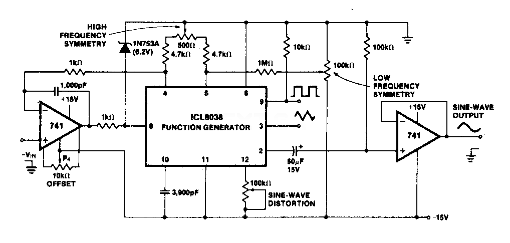
Precision voltage controlled oscillator
The linearity of the input sweep voltage in relation to the output frequency is significantly enhanced by utilizing an operational amplifier.
The utilization of an operational amplifier (op-amp) in electronic circuits is a common practice to improve the linearity of input-output...
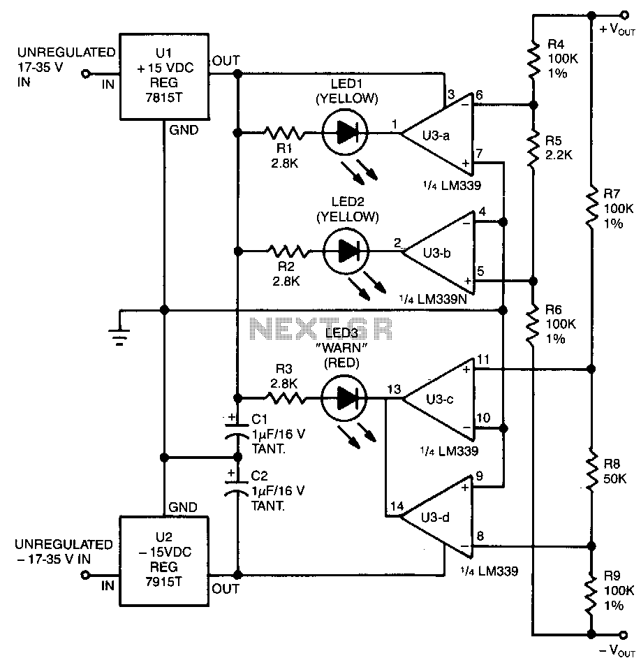
Power-supply-balance-indicator
This circuit utilizes two pairs of comparators from an LM339N quad comparator. One pair controls the yellow positive (+) and negative (-) indicators, while the other pair drives the red warning LED3. The circuit is powered by the unregulated section...
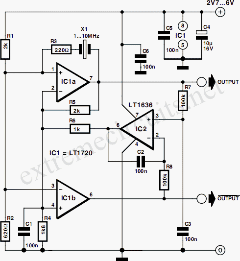
Comparator Based Crystal Oscillator
A simple crystal oscillator can be constructed using a comparator from the LT1720/LT1721 series; however, this design may encounter several inherent limitations and issues. While the LT1720/LT1721 provides the correct logic output when one input falls outside the common mode...
%2Busing%2Bop%2Bamp%2B741%2Bic%2B.png "Zero Crossing Detector ZCD Comparator circuit using 741 op amp circuit")
Zero Crossing Detector (ZCD): Comparator circuit using 741 op amp
A zero crossing detector (ZCD) is a voltage comparator that switches its output between +Vsat and -Vsat (where Vsat is the saturation voltage, approximately 14V) when the input crosses the zero reference voltage. Comparators are fundamental operational amplifier circuits that...
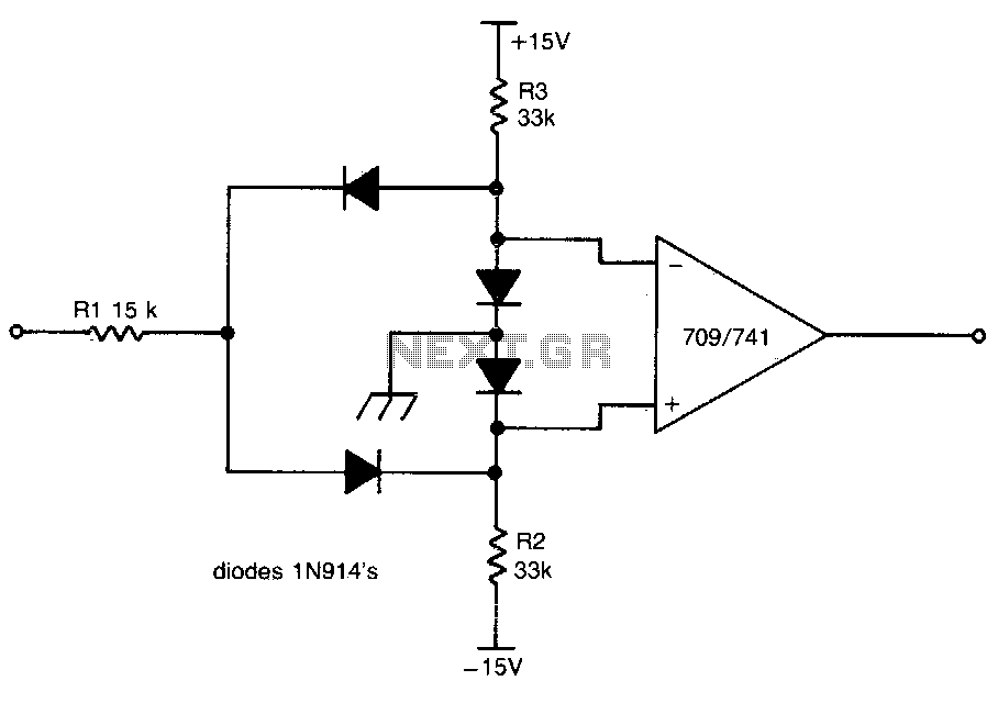
Dual limit comparator
This circuit provides a positive output when the input voltage exceeds 8 volts. Within these limits, the output remains negative. The threshold for the positive output is set by the ratio of resistors R1 and R2, while the threshold for...
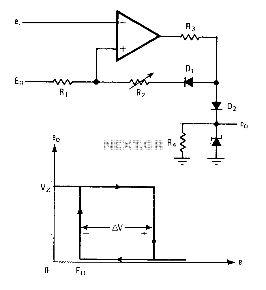
Comparator with variable hysteresis
An operational amplifier can be utilized as an effective device for analog comparator applications that necessitate two distinct trip points. The incorporation of a positive feedback network introduces a precise variable hysteresis into the conventional comparator switching action. This feedback...
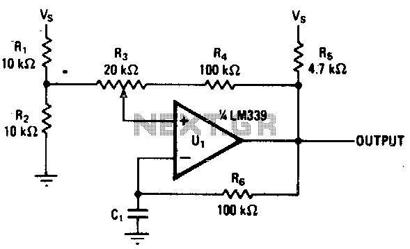
Tunable single comparator oscillator
Varying the amount of hysteresis in this comparator circuit allows for smooth adjustment of output frequencies within the range of 740 Hz to 2 kHz. The hysteresis level, in combination with the time constant formed by resistor R6 and capacitor...
Voltage Controlled Oscillator
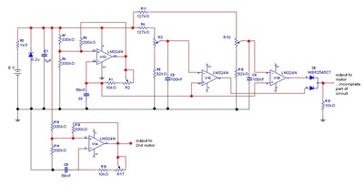
The goal is to control the speed of a 6-volt brush DC motor using a linear potentiometer and to create an oscillating speed effect, with the oscillation frequency also adjustable via a linear potentiometer. The desired complete cycle peak-to-peak duration...